
The REX (ELECTROLUX) RI285/2TL is a 285 liters fridge freezer incorporated model.
Is a simple model (as should be) easy appliance running with the R12 refrigerant.
Here is his history:

The compressor was running very noisy & HOT and was running almost ever without stopping.
As far I know the refrigerator was running 24H day for YEARS and rarely stopped manually by the owner to defrost it. This because the termostat was gone and the door gasket was in bad shape and condenser was full of dust and crap.
Further it was leaking water on the floor due to a broken burnt defrost pan.
Here shown what I've found after 21 years !


REX (ELECTROLUX) RI285/2TL AFTER MY RESTORING:

Now the REX (ZANUSSI-ELECTROLUX) RI285/2TL runs good cooling quiet job without issues.
Lets see modern crap lasting in a heavy cooking way like this REX (ELECTROLUX) RI285/2TL today.
And this is an example on how R12 FRIDGES are undestroyable machines, expecially these models here shown which are dayly thrown away in "recycling crapcenters without justice !
People today just buy fancy fridgephone models time bombs.


Quality of materials is clearly shown after cleanings.
NOTE:Many if not all people have had the common idea to dump it.........sometime a rare chance is given.......to be opposite at the so called normality....................... this here is the example of what i mean for..... opposite. IT WORKS !


REX (ELECTROLUX) RI285/2TL COMPRESSOR ZEM E88601 R12. 180 watt.
The REX (ELECTROLUX) RI285/2TL It's last REX-ELECTROLUX model series refrigerator using the FREON12 R-12 (chlorofluorocarbons) refrigerant.............all after models are running R134 and all moderns the R600A................All evaporators here in this model are in quality heavy alluminium.
The REX (ELECTROLUX) RI285/2TL was first refrigerator model series with Having a Heat Exchanger Adhesively Secured to the Wall of the Refrigerating Compartment
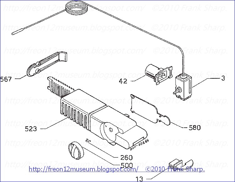


REX (ELECTROLUX) RI285/2TL THERMOSTAT:K59L1260FF (2262154038)
Temperature control with SPST switch and auxiliary switch
for OFF position. Automatic defrost function by constant cut-in value.
for OFF position. Automatic defrost function by constant cut-in value.
Terminal 3-4 closes at temperature rise
Terminal 3-6 opens in OFF position (version C without auxiliary terminal 6)
Terminal 3-6 opens in OFF position (version C without auxiliary terminal 6)
Closing with rising temperature and auxiliary switch (terminal 3-6) connected in series with the main switch breaks the current circuit as soon as the temperature control is set to OFF position.
The main feature of the temperature control K59 is the cut-out point adjustable via the dial shaft and the cut-in point remaining constant in all positions. As this cut-in point normally is in the positive range, automatic defrosting is initiated during each compressor stop period.
 In general type K59 is classified into 3 basic versions:
Version A: as desbribed above
Version B: as desbribed above, but with so-called bellows heater. This is a metal film resistor (82 kΩ) connected in paralle to the main switch, which when the main switch is open (compressor stop period), heats the control housing and bellows (diaphragm) of the capillary system. By this the X-ambient effect (crossing of ambient temperature) is avoied in the compressor stop period, i.e. defrost period of the evaporator.
Heating of the bellows ensures that the defrost sensing point at the evaporator is the coldest point of the capillary system. Perfect function of the temperature control is guaranteed.
Version C: without bellows heater and without auxiliary switch for cut-out.
Version C: without bellows heater and without auxiliary switch for cut-out.
There is a possibility to choose between the type with wnd that without OFF position. OFF position here means manual opening of the main switch 3-4 within a dial angle of 45° and at the same time mechanical locking.
The thermals of the thermostats identify the trend of the temperature in function of the knob
position.
The cut-out thermal interrupts th e compressor power, while the cut-in thermal powers the
compressor.
position.
The cut-out thermal interrupts th
e compressor power, while the cut-in thermal powers thecompressor.
The “min” position of the thermostat knob corresponds to the highest temperatures (generally
indicated with no. 1).
The “max” position of the thermostat knob corresponds to the lowest temperatures (generally
indicated with no. 6).

The cut-in and cut-out thermals can have a “linear” or “bent” trend. In case of replacement of
a thermostat with a “linear” thermal with one having a “bent” thermal or vice-versa, you
 need
needto consider that, in the intermediate positions, the temperatures of the “bent” thermal are
lower if compared to the temperatures of the “linear” thermal.
The sleeve used for covering the capillary has two functions:
- to guarantee the safety of the users against electric shocks in case
the capillary comes close to electric components;
- to g
 uarantee the functionality of the appliance so as the capillary
does not come into contact with cold parts, thus bypassing the
reading of the bulb.
REX (ELECTROLUX) RI285/2TL REFRIGERATING APPLIANCE WITH SINGLE THERMOSTATIC TEMPERATURE CONTROL DEVICE:
The
present invention relates to a refrigerating appliance comprising a
refrigerating circuit provided with a thermostatic temperature control
arrangement.Particularly, but not exclusively, the present invention relates to a multi-temperature refrigerating appliance provided with a single thermostatic temperature control device.
Two-temperature refrigerating appliances are well known, having two main compartments which are kept at different temperatures and provided with independent access doors. Usually, one of the compartments is maintained at an average temperature of about + 5 DEG C for preserving fresh goods, whereas the other compartment is maintained at an average temperature of about - 18 DEG C for freezing purposes.
Preferably, such refrigerating appliances utilize one single-compressor refrigerating circuit in which two evaporators associated with relevant storage and freezer compartments are connected in series. An embodiment of this kind is for instance disclosed in EP-A-0 298 349.
The temperature in the refrigerating appliance, determined by alternate operative and inoperative phases of the compressor, is usually controlled by means of a single thermostatic control device which is capable of sensing, directly or indirectly, the temperature of the evaporator associated with the storage compartment.
More particularly, the compressor is actuated when the temperature of the storage compartment evaporator exceeds a given maximum value and is deenergized, in order to perform a corresponding defrost phase of the storage compartment evaporator, when the above temperature falls below a predetermined minimum value. The temperature inside the compartments depends on the ON/OFF ratio in the operating cycle of the compressor, as well as on the general dimensions of the refrigerating appliance, its loading conditions and the ambient temperature.
It is known, in this condition, that when the ambient temperature is particularly low the thermostatic control device makes the compressor run with correspondingly reduced operative phases with respect to the inoperative phases, in order to maintain the predetermined average temperature of approx. + 5 DEG C in the storage compartment. Under these operating conditions, therefore, the freezer compartment is likely to be cooled insufficiently by the associated evaporator, with a consequent deterioration of the goods contained in the freezer compartment itself. Anyway, the long inoperative phases of the compressor in case of particularly low ambient temperature cause undesirably wide temperature fluctuations to occur in both compartments, and this is in contrast with a desirable correct operation.
In order to overcome the above drawbacks it is common practice to provide a so-called "balancing" heating element (consisting of a heating resistance, for example) in the storage compartment, the heating element being controlled by the thermostatic control device to be actuated in place of the compressor during the inoperative phases of the compressor itself.
The amount of heat generated by the balancing resistance during the defrost phases of the storage compartment evaporator artificially compensated for the low ambient temperature, in this way promoting a better ratio between the ON and OFF phases of the compressor, thus enabling the freezer compartment to be refrigerated correctly and causing narrower temperature fluctuations to occur in both compartments.
REX (ELECTROLUX) RI285/2TL Refrigerating apparatus having a heat exchanger adhesively secured to the wall of the refrigerating compartment.
 A refrigerating apparatus, particularly of the domestic type, comprising
a refrigerating compartment (7) having walls of a plastic material, and
a panel-shaped metal evaporator (5) secured in contact with a wall (6)
of the refrigerating compartment (7) by the interposition therebetween
of a double-faced adhesive film For permitting the evaporator to be
constructed without dimensional limits the thermal transition surfaces
between the heat exchanger panel (5) and the wall (6) are provided with
expansion joints (8A, 8B; 10).
A refrigerating apparatus, particularly of the domestic type, comprising
a refrigerating compartment (7) having walls of a plastic material, and
a panel-shaped metal evaporator (5) secured in contact with a wall (6)
of the refrigerating compartment (7) by the interposition therebetween
of a double-faced adhesive film For permitting the evaporator to be
constructed without dimensional limits the thermal transition surfaces
between the heat exchanger panel (5) and the wall (6) are provided with
expansion joints (8A, 8B; 10).
Refrigerating Apparatus Having a Heat
Exchanger Adhesively Secured to the Wall of the
Refrigerating Compartment Patent Claims:
1. A refrigerating apparatus, particularly of the domestic type, comprising a refrigerating compartment having walls of a plastic material, and at least one panel-shaped heat exchanger made of metal and mounted in contact with a wall of said refrigerating compartment by means of a double-faced adhesive film interposed therebetween, characterized in that the thermal transition surface between said heat exchanger panel (5) and the adjacent wall (6) of said refrigerating compartment (7) is provided with discontinuities (8A, 8B; 10) acting as expansion joints.
2. A refrigerating apparatus according to claim 1, characterized in that said discontinuities are formed as incisions (8A, 8B) passing transversely through the body of said heat exchanger panel (5).
3. A refrigerating apparatus according to claim 1, characterized in that said discontinuities are formed as recessed areas (10) in said wall (6) of said refrigerating compartment (7) at the side facing towards said heat exchanger panel (5) ot positions determining interruptions of the continuity between areas (9) of said wall (6) contacting said heat exchanger panel (5) and between said areas (9) and adjacent surfaces of said wall (6) not in contact with said panel (5).
Description:
Description The present invention re lates to a refrigerating
apparatus, particularly of the domestic type, comprising an evaporator
acting as a heat exchanger made of metal and adhesively secured to the
outer surface of a wall of a refrigerating compartment formed of a
plastic material.
lates to a refrigerating
apparatus, particularly of the domestic type, comprising an evaporator
acting as a heat exchanger made of metal and adhesively secured to the
outer surface of a wall of a refrigerating compartment formed of a
plastic material.
In a refriegrator of this type, the rear wall of the refrigerating compartment and the surface of the evaporator participating in the thermal transition process are of planar configuration and connected in close contact with each other by means of a double-faced adhesive sheet or film interposed therebetween.
It is noted that the plastic material of which the refrigerating compartment is made (usually polystyrene) has a thermal expansion coefficient which is about three times that of the material of the evaporator (usually aluminum).
Variations of temperature (for instance during transport of the apparatus, on starting operation of the apparatus for the first time, or during normal operation thereof) thus result in different expansion of the two components, which has to be accommodated by the double-faced adhesive film. The latter is selected to have an infinitesimally small thickness (about ten hundredth of a millimeter) so as not to interfere with the thermal exchange process, and al so for economical reasons, in that a double-faced adhesive film of
greater thickness, and thus more expensive, although ensuring a
reliable mechanical connection, would excessively interfere with the
thermal exchange process.
so for economical reasons, in that a double-faced adhesive film of
greater thickness, and thus more expensive, although ensuring a
reliable mechanical connection, would excessively interfere with the
thermal exchange process.
In the course of laboratory experiments it has been found that the different expansion of an evaporator made of aluminium and a wall made of polystyrene can be accommodated by this type of double-faced adhesive film only with an evaporator the surface dimensions of which do not exceed a certain value, for instance an area of about 30x40 cm.
The different expansion characteristics of these two materials have thus formerly limited the construction of evaporators to the dimensions stated above, or even smaller dimensions. In refrigerators requiring the use of evaporators of greater dimensions, the double-faced adhesive film had to be replaced by more complicated and expensive connection systems. In this context it is known from German Patent No. 3,329,614 to accomplish the connection between the wall of the refrigerating compartment and the heat exchanger or evaporator by interposing therebetween a layer of a gel-type viscous thixotropic material. This solution involves the employ of a difficultly treatable material, of suitable sealing means, and in many cases of additional supply containers for compensating possible losses of the connecting substance.
This solution thus complicates the construction of the refrigerator while reducing, although not eliminating, the employ of adhesive substances.
It is therefore an object of the invention to achieve, soleley by the employ of the described double-faced adhesive film, an optimum interconnection between a cell made of a plastics material and an evaporator made of metal and having a greater surface area than formerly admissible with regard to the adhesive capacity of the double-faced adhesive film.
According to the invention, this object is attained in a refrigerating apparatus, particularly of the domestic type, comprising a refrigerating compartment having walls of a plastic material, and at least one panel-shaped heat exchanger made of metal and mounted in contact with a wall of said refrigerating compartment by means of a doublefaced adhesive film interposed therebetween, characterized in that the thermal transition surface between said heat exchanger panel and the adjacent wall of said refrigerating compartment is provided with discontinuities acting as expansion joints.
The characteristics of the refrigerating apparatus according to the invention will become more clearly evident from the following description, given by way of example with reference to the accompanying drawings, wherein: fig. 1 shows a diagrammatic front view of a metal evapor ator mounted in contact with the refrigerating compartment, fig. 2 shows an alternative embodiment of the refrigerating apparatus according to the invention, depicting in particular a portion of the wall of the refrigerat in compartment from the side not in contact with the evaporator or heat exchanger, and fig. 3 shows a cross-sectional view of a portion of the refrigerating compartment taken along the line 111-111 in Fig. 2.
The figures of the drawing refer to a refrigerating apparatus provided with an evaporator/heat exchanger 5 of the so-called "hidden" type secured to the outer face of a rear wall 6 of a refrigerating compartment 7.
Evaporator/heat exchanger 5 is of the "panel" type made by joining two metal sheets,
preferably of aluminium, for example by the roll-bond method. The
evaporator/heat exchanger may also be formed of a single metal sheet
carrying a meandering tubular conduit secured thereto in a suitable
manner and acting to convey a refrigerant.
Refrigerating compartment 7 is of box-shaped configuration formed preferably of polystyrene by injection molding, vacuum drawing or a similar process.
The connection between evaporator panel 5 and rear wall 6 is accomplished by the interposition therebetween of a double-faced adhesive film (not shown) of an infinitesimally small thickness and having a surface area at least equalling that of evaporator panel 5.
In one embodiment of the refrigerating apparatus according to the invention, the body of evaporator panel 5 is formed with transversely extending incisions 8 passing therethrough (fig. 1). To this purpose, conduits 11 for the refrigerant are formed to follow a course permitting the formation of a cruciform central incision 8A and of four peripheral incisions 8B.
As a result, the expansions and contractibns to which evaporator panel 5 is subjected are no longer directly related to the overall dimensions of its entire surface, but only to the dimensions of the partial surface areas defined by incisions 8 and the outer boundaries of evaporator panel 5.
The incisions 8 thus permit evaporator panel 5 to adapt itself to the greatest expansions and contractions to which plastic wall 6 may be subjected without surpassing the limits of the adhesion capacity of the double-faced adhesive film joining the two components.
It is thus evident that the provision of the incisions 8 in evaporator panel 5 permits the dimensions of the latter to be increased over the limits imposed by the different thermal expansion characteristics of the materials employed and by the adhesion capacity of a double-faced adhesive film of infinitesimally small thickness. Any increase of the dimensions of the surface area of evaporator panel 5 may be accompanied by a corresponding increase of the number of incisions 8 actingas
expansion joints, and thus of the number of partial surface areas
defined therebetween.
Shown in figs. 2 and 3 is an alternative embodiment of the refrigerating apparatus according to the invention. In this case evaporator panel 5 may be of conventional construction, that is, not provided with incisions 8, while rear wall 6 of refrigerating compartment 7 is of a modified construction.
In particular, as shown in the cross-sectional view of fig. 3, the area of rear wall 6 coming into contact with evaporator panel 5 is formed with raised surface portions 9 projecting rearwards of rear wall 6 towards evaporator panel 5. Raised surface portions 9 may by way of example be of quadrangular shape, but may of course also have any other suitable configuration.
In this second embodiment, the different thermic behaviour of the two bonded elements is compensated by peripheral areas 10 of each raised surface area 9. In effect these areas 10 act as deformable diaphragms permitting plastic wall 6 to adapt itself to the smaller expansion and contraction of the metal evaporator panel 5.
Both of the described solutions permit an optimum bond to be achieved between a wall of a plastics material and a metallic heat exchanger by the interposition therebetween of a double-faced adhesive film of infinitesimally small thickness, with the metallic heat exchanger having a surface area of greater dimensions than formerly admissible in view of the adhesion capacity ofa double-faced adhesive film of this type and of the different thermal expansion characteristics of the materials joined thereby. It is obvious that both of the described solutions may be employed in one and the same refrigerating apparatusso as to combine their individual advantages.
The object of the invention is thus attained without the employ of complicated and expensive connection systems or-materials the processing of which is difficult.
lates to a refrigerating
apparatus, particularly of the domestic type, comprising an evaporator
acting as a heat exchanger made of metal and adhesively secured to the
outer surface of a wall of a refrigerating compartment formed of a
plastic material.In a refriegrator of this type, the rear wall of the refrigerating compartment and the surface of the evaporator participating in the thermal transition process are of planar configuration and connected in close contact with each other by means of a double-faced adhesive sheet or film interposed therebetween.
It is noted that the plastic material of which the refrigerating compartment is made (usually polystyrene) has a thermal expansion coefficient which is about three times that of the material of the evaporator (usually aluminum).
Variations of temperature (for instance during transport of the apparatus, on starting operation of the apparatus for the first time, or during normal operation thereof) thus result in different expansion of the two components, which has to be accommodated by the double-faced adhesive film. The latter is selected to have an infinitesimally small thickness (about ten hundredth of a millimeter) so as not to interfere with the thermal exchange process, and al
so for economical reasons, in that a double-faced adhesive film of
greater thickness, and thus more expensive, although ensuring a
reliable mechanical connection, would excessively interfere with the
thermal exchange process.In the course of laboratory experiments it has been found that the different expansion of an evaporator made of aluminium and a wall made of polystyrene can be accommodated by this type of double-faced adhesive film only with an evaporator the surface dimensions of which do not exceed a certain value, for instance an area of about 30x40 cm.
The different expansion characteristics of these two materials have thus formerly limited the construction of evaporators to the dimensions stated above, or even smaller dimensions. In refrigerators requiring the use of evaporators of greater dimensions, the double-faced adhesive film had to be replaced by more complicated and expensive connection systems. In this context it is known from German Patent No. 3,329,614 to accomplish the connection between the wall of the refrigerating compartment and the heat exchanger or evaporator by interposing therebetween a layer of a gel-type viscous thixotropic material. This solution involves the employ of a difficultly treatable material, of suitable sealing means, and in many cases of additional supply containers for compensating possible losses of the connecting substance.
This solution thus complicates the construction of the refrigerator while reducing, although not eliminating, the employ of adhesive substances.
It is therefore an object of the invention to achieve, soleley by the employ of the described double-faced adhesive film, an optimum interconnection between a cell made of a plastics material and an evaporator made of metal and having a greater surface area than formerly admissible with regard to the adhesive capacity of the double-faced adhesive film.
According to the invention, this object is attained in a refrigerating apparatus, particularly of the domestic type, comprising a refrigerating compartment having walls of a plastic material, and at least one panel-shaped heat exchanger made of metal and mounted in contact with a wall of said refrigerating compartment by means of a doublefaced adhesive film interposed therebetween, characterized in that the thermal transition surface between said heat exchanger panel and the adjacent wall of said refrigerating compartment is provided with discontinuities acting as expansion joints.
The characteristics of the refrigerating apparatus according to the invention will become more clearly evident from the following description, given by way of example with reference to the accompanying drawings, wherein: fig. 1 shows a diagrammatic front view of a metal evapor ator mounted in contact with the refrigerating compartment, fig. 2 shows an alternative embodiment of the refrigerating apparatus according to the invention, depicting in particular a portion of the wall of the refrigerat in compartment from the side not in contact with the evaporator or heat exchanger, and fig. 3 shows a cross-sectional view of a portion of the refrigerating compartment taken along the line 111-111 in Fig. 2.
The figures of the drawing refer to a refrigerating apparatus provided with an evaporator/heat exchanger 5 of the so-called "hidden" type secured to the outer face of a rear wall 6 of a refrigerating compartment 7.
Evaporator/heat exchanger 5 is of the "panel" type made
by joining two metal sheets,
preferably of aluminium, for example by the roll-bond method. The
evaporator/heat exchanger may also be formed of a single metal sheet
carrying a meandering tubular conduit secured thereto in a suitable
manner and acting to convey a refrigerant.Refrigerating compartment 7 is of box-shaped configuration formed preferably of polystyrene by injection molding, vacuum drawing or a similar process.
The connection between evaporator panel 5 and rear wall 6 is accomplished by the interposition therebetween of a double-faced adhesive film (not shown) of an infinitesimally small thickness and having a surface area at least equalling that of evaporator panel 5.
In one embodiment of the refrigerating apparatus according to the invention, the body of evaporator panel 5 is formed with transversely extending incisions 8 passing therethrough (fig. 1). To this purpose, conduits 11 for the refrigerant are formed to follow a course permitting the formation of a cruciform central incision 8A and of four peripheral incisions 8B.
As a result, the expansions and contractibns to which evaporator panel 5 is subjected are no longer directly related to the overall dimensions of its entire surface, but only to the dimensions of the partial surface areas defined by incisions 8 and the outer boundaries of evaporator panel 5.
The incisions 8 thus permit evaporator panel 5 to adapt itself to the greatest expansions and contractions to which plastic wall 6 may be subjected without surpassing the limits of the adhesion capacity of the double-faced adhesive film joining the two components.
It is thus evident that the provision of the incisions 8 in evaporator panel 5 permits the dimensions of the latter to be increased over the limits imposed by the different thermal expansion characteristics of the materials employed and by the adhesion capacity of a double-faced adhesive film of infinitesimally small thickness. Any increase of the dimensions of the surface area of evaporator panel 5 may be accompanied by a corresponding increase of the number of incisions 8 acting
as
expansion joints, and thus of the number of partial surface areas
defined therebetween.Shown in figs. 2 and 3 is an alternative embodiment of the refrigerating apparatus according to the invention. In this case evaporator panel 5 may be of conventional construction, that is, not provided with incisions 8, while rear wall 6 of refrigerating compartment 7 is of a modified construction.
In particular, as shown in the cross-sectional view of fig. 3, the area of rear wall 6 coming into contact with evaporator panel 5 is formed with raised surface portions 9 projecting rearwards of rear wall 6 towards evaporator panel 5. Raised surface portions 9 may by way of example be of quadrangular shape, but may of course also have any other suitable configuration.
In this second embodiment, the different thermic behaviour of the two bonded elements is compensated by peripheral areas 10 of each raised surface area 9. In effect these areas 10 act as deformable diaphragms permitting plastic wall 6 to adapt itself to the smaller expansion and contraction of the metal evaporator panel 5.
Both of the described solutions permit an optimum bond to be achieved between a wall of a plastics material and a metallic heat exchanger by the interposition therebetween of a double-faced adhesive film of infinitesimally small thickness, with the metallic heat exchanger having a surface area of greater dimensions than formerly admissible in view of the adhesion capacity ofa double-faced adhesive film of this type and of the different thermal expansion characteristics of the materials joined thereby. It is obvious that both of the described solutions may be employed in one and the same refrigerating apparatusso as to combine their individual advantages.
The object of the invention is thus attained without the employ of complicated and expensive connection systems or-materials the processing of which is difficult.


1. A method for making an evaporator of the roll bond type,
particularly for use in domestic refrigerating appliances, with a frist
step comprising the insertion of a return pipe into a retrun passage
formed between the two bonded sheet layers of the roll bond evaporator, a
second step comprising the compression of said return passage about an
end portion of said return pipe so as to form a narrow substantially
annular space, preferably of a length of at least 20 mm, between the
inner wall of said return passage and the outer face of said return pipe
inserted therein, characterized by the provision of a third step
comprising the injection of a semi-fluid substance having sealing and
adhesive properties into a further passage (9) obtained by suitably
shaping the two sheet layers of the roll bond structure, said further
passage (9) having at one of its ends a port (11) opening into said
space (12), so that and until said substance progressively fills all or
part of the volume of said space.
2. A method according to claim 1, characterized in that said port (11) opens into said space (12) substantially adjacent the bottom thereof.
3. A method according to claim 2, characterized in that said sealing substance is of the anaerobic polymerization type.
4. A method according to claim 3, characterized in that subsequent to the filling of said space (12), the corresponding area of the roll bond structure is subjected to a heat treatment, preferably by induction heating, for the polymerization of said sealing substance.
5. A method according to claim 5, characterized in that said induction heating step is carried out for an interval of about 10 to 20 seconds.
6. A method according to any of the preceding claims, characterized in that said return pipe (1) is retained at a fixed position within said passage (3) during the subsequent three steps of the process.
7. A method according to any of the preceding claims, characterized in that the insertion of said return pipe (1) into said passage (3) is carried out so as to avoid any contact between the two components.
8. A method according to claim 7, characterized in that said space (12) has a width of between o.2 and o.5 mm.
9. A refrigerating appliance provided with at least one evaporator, characterized by being made with the employ of the method according to any of the preceding claims.
Description:
The invention relates to a method for fashioning a detail of
an evaporator of the roll bond type for use in a refrigerating
appliance, particularly of the domestic type, and to a refrigerating
appliance equipped with an evaporator fashioned by employing this
method.
 The invention is in particular applicable to a
refrigerator of the static function type or the forced circulation type,
with a single capillary or twin capillaries. For the sake of
simplicity, the following description will refer to the single-capillary
type, it being understood, however, that the invention is similarly
applicable to refrigerating appliances having more than one evaporator
and a corresponding number of capillaries.
The invention is in particular applicable to a
refrigerator of the static function type or the forced circulation type,
with a single capillary or twin capillaries. For the sake of
simplicity, the following description will refer to the single-capillary
type, it being understood, however, that the invention is similarly
applicable to refrigerating appliances having more than one evaporator
and a corresponding number of capillaries.
In refrigerant circuits for domestic refrigerating appliances of a known type, the capillary and the return pipe are connected to the evaporator by means of a "union" using a length of pipe, preferably aluminum pipe, to be inserted into a suitable cavity formed between the two aluminum sheets of which the well-known "roll bond" evaporator is composed.
As generally known, the employ of the roll bond technique permits the manufacture of the refrigerant circuit to be greatly simplified, although there are certain shortcomings known to those skilled in the art and relating to the method employed for making and connecting the evaporator.
As a matter of fact, in known refrigerating appliances equipped with a roll bond evaporator, the return pipe is compression-fitted thereto by exclusively mechanical means. This fitting technique is unable, however, to guarantee hermetic sealing at pressures of more than about 5 kp/cm<2>, so that under certain circumstances the high-pressure fluid tends to leak from the mechanic connection and to thereby escape from the refrigerant circuit.
The gravest inconvenience resulting from this technique is the possibility of the escape of gaseous refrigerant into the ambient atmosphere. This is because the connection of the return pipe to the return passage of the roll bond evaporator as well as the connection of the capillary to the are generally accomplished by the employ of well known procedures consisting in the compression from the outside of determined portions of the roll bond structure about the return pipe and the capillary at the locations of the return passage and the inlet pasage, respectively, of the roll bond evaporator.
This compression-fitting process may be accompanied by soldering the return pipe to the roll bond structure at the point of entrance, or by the applicationof an adhesive having suitable
characteristics to the surface of the capillary and that of the return
pipe at the respective compression-fitting locations.
The discussed shortcomings derive from the fact that the soldering operation is always a critical process with sometimes uncertain results, and in any case rather costly. For this reason the soldering method is whereever possible replaced by the application of adhesive at the compression-fitting locations.
On the other hand, however, the application of an adhesive to the surface of the return pipe to be inserted into the roll bond structure is not without problems caused for instance by the formation of bubbles in the thin adhesive coating or by the presence of adhesive-free areas resulting from the viscosity of the adhesive or from the adhesive being scraped off by mutual contact between complementary surfaces during the fitting process, which is usually a manual operation. Finally, the manual application of the adhesive may result in the presence of insufficient or excessive amount of adhesive on different surface areas, giving rise to faulty sealing.
The escape of the gaseous refrigerant cannot always be detected in the course of controls during the manufacturing process, particularly in the case of extremely small leaks. The full impact of the defect is thus noticed only after the refrigerating appliance has been put into use, requiring the manufacturer to carry out extremely onerous and laborious service operations, as well known by those skilled in the trade, without any remedy in sight.
The construction and maintenance of refrigerating appliances of this type are thus rendered rather complicated by the described operations which do not, moreover, lend themselves to being readily automatized.
It would therefore be desirable, and is in fact an object of the present invention, to provide a domestic refrigerating appliance in which the above discussed shortcomings are avoided without incurring construction complications or the necessity of novel technologies, so as to maintain low production costs.
These and other objects are attained in a refrigerating appliance as defined in the appended claims.
The invention will be more fully understood from the following description, given by way of example with reference to the accompanying drawings, wherein: fig. 1 is a diagrammatic illustration of a first step in the method according to the invention for sealingly connecting a return pipe to a roll bond evaporator, fig. 2 shows a second step of said method, and fig. 3 shows a third step of said method.

The method according to the invention is carried out in four distinct steps, the first one of which comprises the insertion of a return pipe 1, with a capillary 2 enclosed therein, into a passage 3 formed between the two sheet layers of a roll bond evaporator 4. The insertion of return pipe 1 into passage 3 has to be carried out in a manner ensuring that the two cylindrical elements are maintained substantially coaxial with one another, or at least with their respective surfaces out of contact with one another.
To this purpose the diameter of return pipe 1 is selected to be slightly smaller than that of passage 3, so that a space 12 of preferably about o.2 to o.5 is defined between the two respective surfaces.
As generally known, return pipe 1 is inserted to a predetermined position 5 of its inner end, while a certain length of capillary 2 projecting from the end of return pipe 1 extends through a restriction 6 formed in a linear extension 7 of return pipe receiving passage 3.
This positioning has to be maintained throughout the three subsequent steps of the operation, but then the operations of inserting the components and fixing them in position can be readily and fully automatised by one skilled in the art.
The second step comprises the compression of passage 3 about an end portion 8 of return pipe 1, and of restriction 6 about capillary 2, and is performed in the conventional manner.
The third step of the process comprises the injection of a semi-fluid substance having sealing and adhesive properties into a further passage 9 obtained by suitably shaping the two sheet layers of the roll bond structure. As clearly shown in the drawings, possage 9 has an outwards opening port 10 at one end, and at the other, a port 11 opening into the narrow space 12 defined between passage 3 of the roll bond structure and the length of return pipe 1 inserted thereinto.
It is important that port 11 opens into the bottom portion of space 12 as shown in the drawings.
The pressure applied for the injection of the semi-fluid substance is effective to ensure that the substance progressively and completely fills space 12 so as to fully replace the air originally contained therein, the length of space 12 having been selected with a view to achieving a reliable sealing effect.
It has thus been found that a length of space 12 of at least 30 mm is sufficient to ensure such reliable sealing effect to guard against gas losses, even when space 12 is not completely filled by the injected substance. Even when the air has not been completely displaced from space 12, leaving a small air pocket adjacent the closed end thereof, the desired sealing of the connection will not be impaired.
As a matter of fact, the hermetic sealing of the connection is substantially brought about by the
injected adhesive substance forming an annular diaphragm between, and
bonded to, the outer wall surface of return pipe 1 and the inner wall
surface of passage 3, this diaphragm being impermeable to the passage of
gas from one side thereof to the other.
The formation of an annular diaphragm having the above described sealing properties is ensured by the injection of the sealing substance through the port 11 located, as has been pointed out, closely adjacent the bottom of space 12.
It is preferable to employ a substance of the anaerobic polimerization type and of very low viscosity, and thus capable of penetrating even the smallest gaps of space 12 by capillary action.
Preferred in any case is the employ of a monocomponent anaerobic polymerization substance, for instance TOPFIX NA 84 supplied by CECA company, which requires a certain time for setting at least to a degree permitting the evaporator to be subsequently handled as for mounting it in a refrigerating appliance, without thereby endangering the previously obtained seal.
Since this time interval is usually not available in an automatized manufacturing process with high production rates, it is advisable to provide a fourth step which consists in performing a heat treatment of the area previously supplied with the sealing substance, preferably by subjecting the respective area to induction heating for a very short time, for instance 10 to 20 seconds, by the employ of a technique generally known to those skilled in the art.

At the end of this short period, the return pipe is perfectly sealed to the roll bond structure, so that the evaporator is ready for further processing.
The preceding description has been given on the assumption that the capillary 2 is contained within the return pipe 1. The teaching of the invention still holds valid, however, when the capillary 2 is to be connected to the evaporator independently of the return pipe.
The described method is thus conducive to obtaining the following advantages: a) Rapid establishment of the connection between the return pipe and the evaporator without the need for sealing gaskets or other auxiliary parts, and without the necessity of a soldering step, b) Simplified processing of the roll bond structure, c) Simplification and flexibility of the manufacturing process (to be carried out in separate steps capable of automatization), d) Overall economy of the manufacturing process. e) Above all, the quality of the connection is greatly improved as regards the obtention of a reliable seal, particularly with a view to not readily detectable slow leaks.
It is of course possible to design refrigerating appliances with modifications of what has been described above within the purvieew of the present invention.
In refrigerant circuits for domestic refrigerating appliances of a known type, the capillary and the return pipe are connected to the evaporator by means of a "union" using a length of pipe, preferably aluminum pipe, to be inserted into a suitable cavity formed between the two aluminum sheets of which the well-known "roll bond" evaporator is composed.
As generally known, the employ of the roll bond technique permits the manufacture of the refrigerant circuit to be greatly simplified, although there are certain shortcomings known to those skilled in the art and relating to the method employed for making and connecting the evaporator.
As a matter of fact, in known refrigerating appliances equipped with a roll bond evaporator, the return pipe is compression-fitted thereto by exclusively mechanical means. This fitting technique is unable, however, to guarantee hermetic sealing at pressures of more than about 5 kp/cm<2>, so that under certain circumstances the high-pressure fluid tends to leak from the mechanic connection and to thereby escape from the refrigerant circuit.
The gravest inconvenience resulting from this technique is the possibility of the escape of gaseous refrigerant into the ambient atmosphere. This is because the connection of the return pipe to the return passage of the roll bond evaporator as well as the connection of the capillary to the are generally accomplished by the employ of well known procedures consisting in the compression from the outside of determined portions of the roll bond structure about the return pipe and the capillary at the locations of the return passage and the inlet pasage, respectively, of the roll bond evaporator.
This compression-fitting process may be accompanied by soldering the return pipe to the roll bond structure at the point of entrance, or by the application
of an adhesive having suitable
characteristics to the surface of the capillary and that of the return
pipe at the respective compression-fitting locations.The discussed shortcomings derive from the fact that the soldering operation is always a critical process with sometimes uncertain results, and in any case rather costly. For this reason the soldering method is whereever possible replaced by the application of adhesive at the compression-fitting locations.
On the other hand, however, the application of an adhesive to the surface of the return pipe to be inserted into the roll bond structure is not without problems caused for instance by the formation of bubbles in the thin adhesive coating or by the presence of adhesive-free areas resulting from the viscosity of the adhesive or from the adhesive being scraped off by mutual contact between complementary surfaces during the fitting process, which is usually a manual operation. Finally, the manual application of the adhesive may result in the presence of insufficient or excessive amount of adhesive on different surface areas, giving rise to faulty sealing.
The escape of the gaseous refrigerant cannot always be detected in the course of controls during the manufacturing process, particularly in the case of extremely small leaks. The full impact of the defect is thus noticed only after the refrigerating appliance has been put into use, requiring the manufacturer to carry out extremely onerous and laborious service operations, as well known by those skilled in the trade, without any remedy in sight.
The construction and maintenance of refrigerating appliances of this type are thus rendered rather complicated by the described operations which do not, moreover, lend themselves to being readily automatized.
It would therefore be desirable, and is in fact an object of the present invention, to provide a domestic refrigerating appliance in which the above discussed shortcomings are avoided without incurring construction complications or the necessity of novel technologies, so as to maintain low production costs.
These and other objects are attained in a refrigerating appliance as defined in the appended claims.
The invention will be more fully understood from the following description, given by way of example with reference to the accompanying drawings, wherein: fig. 1 is a diagrammatic illustration of a first step in the method according to the invention for sealingly connecting a return pipe to a roll bond evaporator, fig. 2 shows a second step of said method, and fig. 3 shows a third step of said method.

The method according to the invention is carried out in four distinct steps, the first one of which comprises the insertion of a return pipe 1, with a capillary 2 enclosed therein, into a passage 3 formed between the two sheet layers of a roll bond evaporator 4. The insertion of return pipe 1 into passage 3 has to be carried out in a manner ensuring that the two cylindrical elements are maintained substantially coaxial with one another, or at least with their respective surfaces out of contact with one another.
To this purpose the diameter of return pipe 1 is selected to be slightly smaller than that of passage 3, so that a space 12 of preferably about o.2 to o.5 is defined between the two respective surfaces.
As generally known, return pipe 1 is inserted to a predetermined position 5 of its inner end, while a certain length of capillary 2 projecting from the end of return pipe 1 extends through a restriction 6 formed in a linear extension 7 of return pipe receiving passage 3.
This positioning has to be maintained throughout the three subsequent steps of the operation, but then the operations of inserting the components and fixing them in position can be readily and fully automatised by one skilled in the art.
The second step comprises the compression of passage 3 about an end portion 8 of return pipe 1, and of restriction 6 about capillary 2, and is performed in the conventional manner.
The third step of the process comprises the injection of a semi-fluid substance having sealing and adhesive properties into a further passage 9 obtained by suitably shaping the two sheet layers of the roll bond structure. As clearly shown in the drawings, possage 9 has an outwards opening port 10 at one end, and at the other, a port 11 opening into the narrow space 12 defined between passage 3 of the roll bond structure and the length of return pipe 1 inserted thereinto.
It is important that port 11 opens into the bottom portion of space 12 as shown in the drawings.
The pressure applied for the injection of the semi-fluid substance is effective to ensure that the substance progressively and completely fills space 12 so as to fully replace the air originally contained therein, the length of space 12 having been selected with a view to achieving a reliable sealing effect.
It has thus been found that a length of space 12 of at least 30 mm is sufficient to ensure such reliable sealing effect to guard against gas losses, even when space 12 is not completely filled by the injected substance. Even when the air has not been completely displaced from space 12, leaving a small air pocket adjacent the closed end thereof, the desired sealing of the connection will not be impaired.
As a matter of fact, the hermetic sealing of the connection is substanti
ally brought about by the
injected adhesive substance forming an annular diaphragm between, and
bonded to, the outer wall surface of return pipe 1 and the inner wall
surface of passage 3, this diaphragm being impermeable to the passage of
gas from one side thereof to the other.The formation of an annular diaphragm having the above described sealing properties is ensured by the injection of the sealing substance through the port 11 located, as has been pointed out, closely adjacent the bottom of space 12.
It is preferable to employ a substance of the anaerobic polimerization type and of very low viscosity, and thus capable of penetrating even the smallest gaps of space 12 by capillary action.
Preferred in any case is the employ of a monocomponent anaerobic polymerization substance, for instance TOPFIX NA 84 supplied by CECA company, which requires a certain time for setting at least to a degree permitting the evaporator to be subsequently handled as for mounting it in a refrigerating appliance, without thereby endangering the previously obtained seal.
Since this time interval is usually not available in an automatized manufacturing process with high production rates, it is advisable to provide a fourth step which consists in performing a heat treatment of the area previously supplied with the sealing substance, preferably by subjecting the respective area to induction heating for a very short time, for instance 10 to 20 seconds, by the employ of a technique generally known to those skilled in the art.

At the end of this short period, the return pipe is perfectly sealed to the roll bond structure, so that the evaporator is ready for further processing.
The preceding description has been given on the assumption that the capillary 2 is contained within the return pipe 1. The teaching of the invention still holds valid, however, when the capillary 2 is to be connected to the evaporator independently of the return pipe.
The described method is thus conducive to obtaining the following advantages: a) Rapid establishment of the connection between the return pipe and the evaporator without the need for sealing gaskets or other auxiliary parts, and without the necessity of a soldering step, b) Simplified processing of the roll bond structure, c) Simplification and flexibility of the manufacturing process (to be carried out in separate steps capable of automatization), d) Overall economy of the manufacturing process. e) Above all, the quality of the connection is greatly improved as regards the obtention of a reliable seal, particularly with a view to not readily detectable slow leaks.
It is of course possible to design refrigerating appliances with modifications of what has been described above within the purvieew of the present invention.
ZEM E88601 R12. HERMETIC COMPRESSOR INTERNAL VIEW.
(NOTE: THIS COMPRESSOR MODEL ZEM E88601 R12 (Zanussi Elettromeccanica) WAS DEVELOPED IN THE 70'S, the photographed opened model is a 80's scrapped identical model taken as example and still by me today's on the web!)


REX (ELECTROLUX) RI285/2TL ZEM E88601 R12. HERMETIC COMPRESSOR Lubrication of sealed compressor:
Improved lubrication of sealed compressors having a crankshaft provided
with a longitudinal interior duct and a tubular member coupled to a
lower end of the interior duct and having a substantially cylindrical
upper section and a substantially conical lower section adapted to be
submerged in oil. An upper end of the internal lubrication duct ends in a
first substantially conical section and a second substantially
cylindrical section of variable contour depending upon the profile of
the upper end of the crankshaft. A spring may also be situated inside of
the tubular member.
1. In a sealed
compressor including a sealed casing in which an alternating
motor-driven compressor assembly is housed, the assembly including a
vertical-axis crankshaft provided with a longitudinal interior
lubrication duct communicating with points on an exterior surface of the
crankshaft and with an upper end of the same eccentrically to the axis
of rotation thereof, said assembly also including a tubular member
coupled to a lower end of said interior duct of the crankshaft and
comprising a substantially cylindrical upper section and a substantially
conical lower section adapted to be submerged in oil,
the improvement comprising
an upper end of said interior lubrication duct ending in a first substantially conical section and a second substantially cylindric al
section of variable contour depending upon a profile of the upper end of
the crankshaft, and
al
section of variable contour depending upon a profile of the upper end of
the crankshaft, and
the profile of the upper end of the crankshaft cutting the duct at a transition point between the second substantially cylindrical section of variable contour and the first substantially conical section.
2. In a sealed comp ressor including a sealed casing in
which an alternating motor-driven compressor assembly is housed, the
assembly including a vertical-axis crankshaft provided with a
longitudinal interior lubrication duct communicating with points on an
exterior surface of the crankshaft and with an upper end of the same
eccentrically to the axis of rotation thereof, said assembly also
including a tubular member coupled to a lower end of said interior duct
of the crankshaft and comprising a substantially cylindrical upper
section and a substantially conical lower section adapted to be
submerged in oil,
ressor including a sealed casing in
which an alternating motor-driven compressor assembly is housed, the
assembly including a vertical-axis crankshaft provided with a
longitudinal interior lubrication duct communicating with points on an
exterior surface of the crankshaft and with an upper end of the same
eccentrically to the axis of rotation thereof, said assembly also
including a tubular member coupled to a lower end of said interior duct
of the crankshaft and comprising a substantially cylindrical upper
section and a substantially conical lower section adapted to be
submerged in oil,
the improvement comprising
an upper end of said interior lubrication duct ending in a first substantially conical section and a second substantially cylindrical section of a variable contour depending upon a profile of the upper end of the crankshaft,
a spring situated inside said tubular member,
wherein said spring is constituted by an elastic and resistant wire formed as a closed loop ending with a lower leg extending towards the lower substantially conical portion of the tubular member.
3. In a sealed compres sor including a sealed casing in
which an alternating motor-driven compressor assembly is housed, the
assembly including a vertical-axis crankshaft provided with a
longitudinal interior lubrication duct communicating with points on a
exterior surface of the crankshaft and with an upper end of the same
eccentrically to the axis of rotation thereof, said assembly also
including a tubular member coupled to a lower end of said interior duct
of the crankshaft and comprising a substantially cylindrical upper
section and a substantially conical lower section adapted to be
submerged in oil,
sor including a sealed casing in
which an alternating motor-driven compressor assembly is housed, the
assembly including a vertical-axis crankshaft provided with a
longitudinal interior lubrication duct communicating with points on a
exterior surface of the crankshaft and with an upper end of the same
eccentrically to the axis of rotation thereof, said assembly also
including a tubular member coupled to a lower end of said interior duct
of the crankshaft and comprising a substantially cylindrical upper
section and a substantially conical lower section adapted to be
submerged in oil,
the improvement comprising
an upper end of said interior lubrication duct ending in a first substantially conical section and a second substantially cylindrical section of variable contour depending upon a profile of the upper end of the crankshaft,
a spring situated inside said tubular member,
wherein said spring is constituted by an elastic and resistant wire shaped as a substantially inverted U with two arms and bent according to a profile of the lower conical section of the tubular member.
4. In a sealed compressor including a sealed casing in w hich an alternating motor-driven compressor assembly is housed, the
assembly including a vertical-axis crankshaft provided with a
longitudinal interior lubrication duct communicating with points on an
exterior surface of the crankshaft and with an upper end of the same
eccentrically to the axis of rotation thereof, said assembly also
including a tubular member coupled to a lower end of said interior duct
of the crankshaft and comprising a substantially cylindrical upper
section and a substantially conical lower section adapted to be
submerged in oil,
hich an alternating motor-driven compressor assembly is housed, the
assembly including a vertical-axis crankshaft provided with a
longitudinal interior lubrication duct communicating with points on an
exterior surface of the crankshaft and with an upper end of the same
eccentrically to the axis of rotation thereof, said assembly also
including a tubular member coupled to a lower end of said interior duct
of the crankshaft and comprising a substantially cylindrical upper
section and a substantially conical lower section adapted to be
submerged in oil,
the improvement comprising
an upper end of said interior lubrication duct ending in a first substantially conical section and a second substantially cylindrical section of variable contour depending upon a profile of the upper end of the crankshaft, and
a spring situated inside said tubular member,
wherein said spring is constituted by an elastic and resistant wire shaped substantially as a U with upper free ends joined together and a lower end shaped according to a profile of the lower conical section of the tubular member.
5. In a sealed compressor including a sealed casing in which an alternating motor-driven compressor assembly is housed, the assembly inc luding a vertical-axis crankshaft provided with a
longitudinal interior lubrication duct communicating with points on an
exterior surface of the crankshaft and with an upper end of the same
eccentrically to the axis of rotation thereof, the assembly also
including a tubular member coupled to a lower end of the interior duct
of the crankshaft and comprising a substantially cylindrical upper
section and a substantially conical lower section adapted to be
submerged in oil,
luding a vertical-axis crankshaft provided with a
longitudinal interior lubrication duct communicating with points on an
exterior surface of the crankshaft and with an upper end of the same
eccentrically to the axis of rotation thereof, the assembly also
including a tubular member coupled to a lower end of the interior duct
of the crankshaft and comprising a substantially cylindrical upper
section and a substantially conical lower section adapted to be
submerged in oil,
the improvement comprising
a spring situated inside said tubular member,
wherein said spring is constituted by an elastic and resistant wire formed as a closed loop ending with a lower leg extending towards the lower substantially conical portion of the tubular member.
6. In a sealed compressor including a sealedcasing in
which an alternating motor-drive compressor assembly is housed, the
assembly including a vertical-axis crankshaft provided with a
longitudinal interior lubrication duct communicating with points on an
exterior surface of the crankshaft and with an upper end of the same
eccentrically to the axis of rotation thereof, the assembly also
including a tubular member coupled to a lower end of the interior duct
of the crankshaft and comprising a substantially cylindrical upper
section and a substantially conical lower section adapted to be
submerged in oil,
the improvement comprising
a spring situated inside said tubular member,
wherein said spring is constituted by an elastic and resistant wire shaped as a substantially inverted U with two arms bent according to a profile of the lower conical section of the tubular member.
7. In a sealed compressor including a sealed casing in which an alternating motor-driven compressor assembly is housed, the assembly including a vertical-axis crankshaft provided with a longitudinal interior lubrication duct communicating with points on an exterior surface of the crankshaft and with an upper end of the same eccentrically to the axis of rotation thereof. the assembly also including a tubular member coupled to a lower end of the interior duct of the crankshaft and comprising a substantially cylindrical upper section and a substantially conical lower section adapted to be submerged in oil,
the improvement comprising
a spring situated inside said tubular member,
wherein said spring is constituted by an elastic and resistant wire shaped substantially as a U with upper free ends joined together and a lower end shaped according to a profile of the lower conical section of the tubular member.
the improvement comprising
an upper end of said interior lubrication duct ending in a first substantially conical section and a second substantially cylindric
al
section of variable contour depending upon a profile of the upper end of
the crankshaft, and the profile of the upper end of the crankshaft cutting the duct at a transition point between the second substantially cylindrical section of variable contour and the first substantially conical section.
2. In a sealed comp
ressor including a sealed casing in
which an alternating motor-driven compressor assembly is housed, the
assembly including a vertical-axis crankshaft provided with a
longitudinal interior lubrication duct communicating with points on an
exterior surface of the crankshaft and with an upper end of the same
eccentrically to the axis of rotation thereof, said assembly also
including a tubular member coupled to a lower end of said interior duct
of the crankshaft and comprising a substantially cylindrical upper
section and a substantially conical lower section adapted to be
submerged in oil, the improvement comprising
an upper end of said interior lubrication duct ending in a first substantially conical section and a second substantially cylindrical section of a variable contour depending upon a profile of the upper end of the crankshaft,
a spring situated inside said tubular member,
wherein said spring is constituted by an elastic and resistant wire formed as a closed loop ending with a lower leg extending towards the lower substantially conical portion of the tubular member.
3. In a sealed compres
sor including a sealed casing in
which an alternating motor-driven compressor assembly is housed, the
assembly including a vertical-axis crankshaft provided with a
longitudinal interior lubrication duct communicating with points on a
exterior surface of the crankshaft and with an upper end of the same
eccentrically to the axis of rotation thereof, said assembly also
including a tubular member coupled to a lower end of said interior duct
of the crankshaft and comprising a substantially cylindrical upper
section and a substantially conical lower section adapted to be
submerged in oil, the improvement comprising
an upper end of said interior lubrication duct ending in a first substantially conical section and a second substantially cylindrical section of variable contour depending upon a profile of the upper end of the crankshaft,
a spring situated inside said tubular member,
wherein said spring is constituted by an elastic and resistant wire shaped as a substantially inverted U with two arms and bent according to a profile of the lower conical section of the tubular member.
4. In a sealed compressor including a sealed casing in w
hich an alternating motor-driven compressor assembly is housed, the
assembly including a vertical-axis crankshaft provided with a
longitudinal interior lubrication duct communicating with points on an
exterior surface of the crankshaft and with an upper end of the same
eccentrically to the axis of rotation thereof, said assembly also
including a tubular member coupled to a lower end of said interior duct
of the crankshaft and comprising a substantially cylindrical upper
section and a substantially conical lower section adapted to be
submerged in oil, the improvement comprising
an upper end of said interior lubrication duct ending in a first substantially conical section and a second substantially cylindrical section of variable contour depending upon a profile of the upper end of the crankshaft, and
a spring situated inside said tubular member,
wherein said spring is constituted by an elastic and resistant wire shaped substantially as a U with upper free ends joined together and a lower end shaped according to a profile of the lower conical section of the tubular member.
5. In a sealed compressor including a sealed casing in which an alternating motor-driven compressor assembly is housed, the assembly inc
luding a vertical-axis crankshaft provided with a
longitudinal interior lubrication duct communicating with points on an
exterior surface of the crankshaft and with an upper end of the same
eccentrically to the axis of rotation thereof, the assembly also
including a tubular member coupled to a lower end of the interior duct
of the crankshaft and comprising a substantially cylindrical upper
section and a substantially conical lower section adapted to be
submerged in oil, the improvement comprising
a spring situated inside said tubular member,
wherein said spring is constituted by an elastic and resistant wire formed as a closed loop ending with a lower leg extending towards the lower substantially conical portion of the tubular member.
6. In a sealed compressor including a sealed
casing in
which an alternating motor-drive compressor assembly is housed, the
assembly including a vertical-axis crankshaft provided with a
longitudinal interior lubrication duct communicating with points on an
exterior surface of the crankshaft and with an upper end of the same
eccentrically to the axis of rotation thereof, the assembly also
including a tubular member coupled to a lower end of the interior duct
of the crankshaft and comprising a substantially cylindrical upper
section and a substantially conical lower section adapted to be
submerged in oil, the improvement comprising
a spring situated inside said tubular member,
wherein said spring is constituted by an elastic and resistant wire shaped as a substantially inverted U with two arms bent according to a profile of the lower conical section of the tubular member.
7. In a sealed compressor including a sealed casing in which an alternating motor-driven compressor assembly is housed, the assembly including a vertical-axis crankshaft provided with a longitudinal interior lubrication duct communicating with points on an exterior surface of the crankshaft and with an upper end of the same eccentrically to the axis of rotation thereof. the assembly also including a tubular member coupled to a lower end of the interior duct of the crankshaft and comprising a substantially cylindrical upper section and a substantially conical lower section adapted to be submerged in oil,
the improvement comprising
a spring situated inside said tubular member,
wherein said spring is constituted by an elastic and resistant wire shaped substantially as a U with upper free ends joined together and a lower end shaped according to a profile of the lower conical section of the tubular member.
Description:
BACKGROUND OF THE INVENTION
The present invention relates to improvements in the lubrication system of sealed compressors for cooling fluids.
Sealed compressors for cooling fluids are known which include a sealed casing with an alternating motor-driven compressor assembly housed in the interior thereof, the assembly including a vertical-axis crankshaft provided with a longitudinal interior lubrication duct communicating with various points on the exterior surface of the crankshaft and with an upper end of the same, eccentrically to the axis of rotation thereof. The assembly also includes a tubular device coupled to a lower end of the interior duct of the crankshaft, such tubular device having a first upper section substantially cylindrical and a second substantially conical section with an end having an orifice for the introduction of oil.
In such compressors, the oiling of the parts that are in friction is accomplished by means of the oil fluid supplied by the tubular device, which, when rotating and immersed in an oil mass, produces by centrifugal force the raising of the oil through the interior duct of the crankshaft towards the oiling points of the mechanism. Part of the oil exits out of the eccentric orifice at the upper end of the crankshaft, propelled against the interior surface of the sealed casing of the compressor.
There are various patents that disclose particular details of this oiling or lubricating system. U.S. Pat. No. 3,410,478 discloses a cylindrical tubular device joined by a conical section, as well as a wall placed in the interior of the tubular device acting as a gate, such a wall being costly to construct. U.S. Pat. No. 3,451,615 discloses a lateral outflow passage from an eccentric upper section of the interior duct of the crankshaft.
Lastly, Spanish Patent No. 504,039 discloses a channel in the extreme upper face of the crankshaft, arguing the lower cost of constructing such a channel in relation to the lateral outflow passage disclosed in the aforementioned U.S. Pat. No. 3,451,615.
It has been possible to confirm that the current solutions of tubular pumping devices lose part of their effectiveness as the compressor's operating temperature rises. Under these conditions, the fluidity of the oil mass deposited in the housing of the compressor reaches a point such that the oil mass loses velocity of rotation in relation to the velocity of rotation of the tubular device. Such device loses effectiveness as a centrifugal pump due to sliding between the interior wall of the tubular device and the layer of oil in contact with the wall.
The aforementioned interior wall that acts as a gate may, in part, solve the problem described, but it has the drawback of having a high cost of construction. Moreover, the orifice at the upper end of the crankshaft should have a certain form, so that the oil that exits therefrom has sufficient force to be propelled against the interior wall of the sealed casing of the compressor. This certain form, in the compressors that are known, entails significant difficulties in construction.
SUMMARY OF THE INVENTION
With the improvements of the invention, the noted drawbacks can be eliminated.
Accordingly, it is an object of the present invention to eliminate the drawbacks noted above with respect to the prior art.
It is also an object of the present invention to simplify the lubrication of compressors.
It is another object of the present invention to lower manufacturing cost of a lubrication system for compressors.
It is a further object of the present invention to compensate for the decrease in oil viscosity caused by a rise in temperature in the lubrication system of a compressor.
These and other objects are attained by the present invention which is directed to improvements in the lubrication system of compressors for cooling fluids. According to the present invention, the upper end of the interior lubrication duct in a crankshaft of the compressor ends in a first substantially conical section and a second substantially cylindrical section of variable contour depending upon the profile of the upper end of the crankshaft. This distinct configuration of the upper end of the lubrication duct offers the advantage of greater simplicity in construction and consequently a lower manufacturing cost, while at the same time maintaining the same efficiency as other current forms of more complicated configuration.
Advantageously, the tubular device, which is coupled to the lower end of the interior duct of the crankshaft, is provided in its interior with a spring formed by an elastic and resistant wire affixed by means of pressure and by insertion of a part of the spring in a substantially conical section of the tubular device or member submerged in oil (the tubular device comprises a
first substantially cylindrical upper section and a second
substantially conical lower section adapted to be inserted into oil).
The part of the spring submerged in the oil acts as a paddle propelling
the oil, and thereby compensating for decrease in oil viscosity caused
by the temperature.
The aforementioned spring may have various forms or structures in accordance with the present invention. In one embodiment, the spring forms a closed loop which ends with a lower leg thereof extending towards the lower substantially conical portion of the tubular device or member. In a second embodiment, the spring takes the form of two arms making a substantially inverted U, and bent according to the conical profile of the tubular device. In another embodiment, the spring takes the form of two arms shaped in a U and bent according to the conical profile of the tubular device and with the free ends thereof joined at the upper portion thereof.
All the noted spring shapes may be constructed with wire having a circular or a square cross-section so as to improve the attachment thereof within the interior of the tubular device or member.
BRIEF DESCRIPTION OF THE DRAWINGS
For a fuller understanding thereof, the present invention will be described in greater detail below with reference to the accompanying drawings in which certain embodiments of the present invention are schematically illustrated and to which the present invention is not intended to be exclusively restricted.
In the drawings,
FIG. 1 illustrates a longitudinal sectional view of a sealed compressor of cooling fluids, in which the improvements according to the present invention are applied;
FIG. 2 is a partially sectional side view of a crank shaft and of a tubular device having the improvements according to the present invention; and
FIGS. 3 and 4 each illustrate springs for the tubular device illustrated in FIG. 2.

DESCRIPTION OF THE PREFERRED EMBODIMENTS
Referring to FIG. 1, a compressor 1 includes a sealed casing 2 with an alternating motor-driven compressor assembly housed in the interior thereof, the assembly including a vertical-axis crankshaft 3 provided with a longitudinal interior lubrication duct 4 (FIG. 2) communicating with various points 5,6 on the exterior surface of the crankshaft 3, and with the upper end 7 of the same, eccentrically to the axis of rotation thereof. The assembly also includes a tubular device 8 coupled to a lower end of the interior duct 4 of the crankshaft 3, the tubular device 8 comprising a first upper section 9 that is substantially cylindrical and a second lower substantially conical section 10 to be submerged in oil.
As can be seen in FIG. 2, the upper end 7 of the lubrication duct 4 terminates in a first substantially conical section 11 and a second substantially cylindrical section 12 of variable contour depending upon the profile 13 of the upper end 7 of the crankshaft 3.
As also illustrated in FIG. 2, the tubular device 8 is provided in the interior with a spring 14 formed by an elastic and resistant wire, e.g. of tempered steel, and affixed by means of pressure and by insertion of part of the spring in the conical section 10 of the tubular device or member 8 which is adapted to be submerged in the oil. As shown in FIG. 2, the spring 14 takes the form of two arms 15 and 16 shaped into an inverted U and bent at points 17 and 18 according to the conical profile of the tubular device or member 8.
In FIG. 3, the spring 14 forms a closed loop 19 ending with a lower leg 20 thereof extending towards the lower conical part 10 of the tubular device 8.

The spring illustrated in FIG. 4 takes the form of two arms 21 and 22 in the shape of a U bent at points 23 and 24 according to the conical profile of the tubular device 8 (i.e. the lower substantially conical section 10 thereof) and with the free ends 25 and 26 thereof joined at the upper portion as illustrated.
As described above, the springs are introduced into the tubular device 8 with the lower portion thereof situated in the conical section 10 to be submerged in oil. When the crankshaft 3 rotates, driven by the rotor of the electrical motor, the tubular device 8 rotates along with spring 14, with the lower part of the spring submerged in oil acting as a paddle.
The characteristic form 11 of the outflow orifice in the upper end 7 of the lubrication duct 4 permits the oil that flows through the eccentric duct 4 to be propelled in a continuous jet against the interior wall of the casing 2.
It follows from the description above that the improvements according to the present invention allow for enhancement in the lubrication of the crankshaft and in the propulsion of oil against the interior wall of the casing 2 due to the springs 14 acting as paddles, and allows for a reduction in the cost of manufacture of the crankshaft 3 by simplifying the orifice at the upper end 7 of the crankshaft 3 without diminishing the effectiveness thereof. Similarly, the cost of construction of the spring 14 is much lower than the previously described interior wall with respect to the prior art.
The preceding description of the present invention is merely exemplary, and is not intended to limit the scope thereof in any way.
The present invent
ion relates to improvements in the lubrication system of sealed compressors for cooling fluids. Sealed compressors for cooling fluids are known which include a sealed casing with an alternating motor-driven compressor assembly housed in the interior thereof, the assembly including a vertical-axis crankshaft provided with a longitudinal interior lubrication duct communicating with various points on the exterior surface of the crankshaft and with an upper end of the same, eccentrically to the axis of rotation thereof. The assembly also includes a tubular device coupled to a lower end of the interior duct of the crankshaft, such tubular device having a first upper section substantially cylindrical and a second substantially conical section with an end having an orifice for the introduction of oil.
In such compressors, the oiling of the parts that are in friction is accomplished by means of the oil fluid supplied by the tubular device, which, when rotating and immersed in an oil mass, produces by centrifugal force the raising of the oil through the interior duct of the crankshaft towards the oiling points of the mechanism. Part of the oil exits out of the eccentric orifice at the upper end of the crankshaft, propelled against the interior surface of the sealed casing of the compressor.
There are various patents that disclose particular details of this oiling or lubricating system. U.S. Pat. No. 3,410,478 discloses a cylindrical tubular device joined by a conical section, as well as a wall placed in the interior of the tubular device acting as a gate, such a wall being costly to construct. U.S. Pat. No. 3,451,615 discloses a lateral outflow passage from an eccentric upper section of the interior duct of the crankshaft.
Lastly, Spanish Patent No. 504,039 discloses a channel in the extreme upper face of the crankshaft, arguing the lower cost of constructing such a channel in relation to the lateral outflow passage disclosed in the aforementioned U.S. Pat. No. 3,451,615.
It has been possible to confirm that the current solutions of tubular pumping devices lose part of their effectiveness as the compressor's operating temperature rises. Under these conditions, the fluidity of the oil mass deposited in the housing of the compressor reaches a point such that the oil mass loses velocity of rotation in relation to the velocity of rotation of the tubular device. Such device loses effectiveness as a centrifugal pump due to sliding between the interior wall of the tubular device and the layer of oil in contact with the wall.
The aforementioned interior wall that acts as a gate may, in part, solve the problem described, but it has the drawback of having a high cost of construction. Moreover, the orifice at the upper end of the crankshaft should have a certain form, so that the oil that exits therefrom has sufficient force to be propelled against the interior wall of the sealed casing of the compressor. This certain form, in the compressors that are known, entails significant difficulties in construction.
SUMMARY OF THE INVENTION
With the improvements of the invention, the noted drawbacks can be eliminated.
Accordingly, it is an object of the present invention to elim
inate the drawbacks noted above with respect to the prior art. It is also an object of the present invention to simplify the lubrication of compressors.
It is another object of the present invention to lower manufacturing cost of a lubrication system for compressors.
It is a further object of the present invention to compensate for the decrease in oil viscosity caused by a rise in temperature in the lubrication system of a compressor.
These and other objects are attained by the present invention which is directed to improvements in the lubrication system of compressors for cooling fluids. According to the present invention, the upper end of the interior lubrication duct in a crankshaft of the compressor ends in a first substantially conical section and a second substantially cylindrical section of variable contour depending upon the profile of the upper end of the crankshaft. This distinct configuration of the upper end of the lubrication duct offers the advantage of greater simplicity in construction and consequently a lower manufacturing cost, while at the same time maintaining the same efficiency as other current forms of more complicated configuration.
Advantageously, the tubular device, which is coupled to the lower end of the interior duct of the crankshaft, is provided in its interior with a spring formed by an elastic and resistant wire affixed by means of pressure and by insertion of a part of the spring in a substantially conical section of the tubular device or member submerged in oil (the tubular devic
e comprises a
first substantially cylindrical upper section and a second
substantially conical lower section adapted to be inserted into oil).
The part of the spring submerged in the oil acts as a paddle propelling
the oil, and thereby compensating for decrease in oil viscosity caused
by the temperature. The aforementioned spring may have various forms or structures in accordance with the present invention. In one embodiment, the spring forms a closed loop which ends with a lower leg thereof extending towards the lower substantially conical portion of the tubular device or member. In a second embodiment, the spring takes the form of two arms making a substantially inverted U, and bent according to the conical profile of the tubular device. In another embodiment, the spring takes the form of two arms shaped in a U and bent according to the conical profile of the tubular device and with the free ends thereof joined at the upper portion thereof.
All the noted spring shapes may be constructed with wire having a circular or a square cross-section so as to improve the attachment thereof within the interior of the tubular device or member.
BRIEF DESCRIPTION OF THE DRAWINGS
For a fuller understanding thereof, the present invention will be described in greater detail below with reference to the accompanying drawings in which certain embodiments of the present invention are schematically illustrated and to which the present invention is not intended to be exclusively restricted.
In the drawings,
FIG. 1 illustrates a longitudinal sectional view of a sealed compressor of cooling fluids, in which the improvements according to the present invention are applied;
FIG. 2 is a partially sectional side view of a crank shaft and of a tubular device having the improvements according to the present invention; and
FIGS. 3 and 4 each illustrate springs for the tubular device illustrated in FIG. 2.

DESCRIPTION OF THE PREFERRED EMBODIMENTS
Referring to FIG. 1, a compressor 1 includes a sealed casing 2 with an alternating motor-driven compressor assembly housed in the interior thereof, the assembly including a vertical-axis crankshaft 3 provided with a longitudinal interior lubrication duct 4 (FIG. 2) communicating with various points 5,6 on the exterior surface of the crankshaft 3, and with the upper end 7 of the same, eccentrically to the axis of rotation thereof. The assembly also includes a tubular device 8 coupled to a lower end of the interior duct 4 of the crankshaft 3, the tubular device 8 comprising a first upper section 9 that is substantially cylindrical and a second lower substantially conical section 10 to be submerged in oil.
As can be seen in FIG. 2, the upper end 7 of the lubrication duct 4 terminates in a first substantially conical section 11 and a second substantially cylindrical section 12 of variable contour depending upon the profile 13 of the upper end 7 of the crankshaft 3.
As also illustrated in FIG. 2, the tubular device 8 is provided in the interior with a spring 14 formed by an elastic and resistant wire, e.g. of tempered steel, and affixed by means of pressure and by insertion of part of the spring in the conical section 10 of the tubular device or member 8 which is adapted to be submerged in the oil. As shown in FIG. 2, the spring 14 takes the form of two arms 15 and 16 shaped into an inverted U and bent at points 17 and 18 according to the conical profile of the tubular device or member 8.
In FIG. 3, the spring 14 forms a closed loop 19 ending with a lower leg 20 thereof extending towards the lower conical part 10 of the tubular device 8.

The spring illustrated in FIG. 4 takes the form of two arms 21 and 22 in the shape of a U bent at points 23 and 24 according to the conical profile of the tubular device 8 (i.e. the lower substantially conical section 10 thereof) and with the free ends 25 and 26 thereof joined at the upper portion as illustrated.
As described above, the springs are introduced into the tubular device 8 with the lower portion thereof situated in the conical section 10 to be submerged in oil. When the crankshaft 3 rotates, driven by the rotor of the electrical motor, the tubular device 8 rotates along with spring 14, with the lower part of the spring submerged in oil acting as a paddle.
The characteristic form 11 of the outflow orifice in the upper end 7 of the lubrication duct 4 permits the oil that flows through the eccentric duct 4 to be propelled in a continuous jet against the interior wall of the casing 2.
It follows from the description above that the improvements according to the present invention allow for enhancement in the lubrication of the crankshaft and in the propulsion of oil against the interior wall of the casing 2 due to the springs 14 acting as paddles, and allows for a reduction in the cost of manufacture of the crankshaft 3 by simplifying the orifice at the upper end 7 of the crankshaft 3 without diminishing the effectiveness thereof. Similarly, the cost of construction of the spring 14 is much lower than the previously described interior wall with respect to the prior art.
The preceding description of the present invention is merely exemplary, and is not intended to limit the scope thereof in any way.
REX (ELECTROLUX) RI285/2TL Hermetically enclosed compressor with mechanical and electrical connection means:
For an electrically opera
ted, hermetically enclosed compressor (2)
particularly for use in domestic refrigerators there is provided a novel
system for the electric connection of the compressor (2) to the
electric circuit of the refrigerator by means of a single support and
fixation system (13) on the compressor which may be used for
alternatively connecting two different components, one such component
being a conventional support adapted to receive onle the power supply
cables for the compressor, the other component comprising a complete
terminal strip (23) to which all the circuits of the refrigerator are
connected and which is designed for the automatized mounting thereon of
an electric connector.
1. Hermetically enclosed compressor (2) with a mounting base
(13) secured to the compressor for carrying the electrical connections,
characterized by
a support member (26) which is dismountably attached to the compressor (2) and formed as a single module adapted to hold a starter (20) and a thermal protection device (21); and
two different cable connection members, one being a terminal strip (22) and the other being a cable clamping insert (24), the mounting base (13), the terminal strip (22) and the cable clamping insert (24) being formed such that the terminal strip (22) and the cable clamping insert (24) are selectively mountable on the mounting base (13).
2. Compressor according to claim 1, characterized in that there is provided a housing (25) to cover the support member (26) and the cable connection member (22 or 24).
Description:
The present invention relates to a hermetically enclosed compressor according to DE-B-26 04 764.
According to the actual state of the art, the design of the electric connection of such compressors is fundamentally dictated by the design of the electric circuit of the refrigerator as a whole.
The innumerable possibilities of designing an electric circuit for a domestic refrigerator manufactured on an industrial scale may be basically reduced to just two alternative arrangements: the first of these arrangements is directed to the provision at any suitable location within the refrigerator of a suitable terminal strip or box so as to be accessible from the exterior, usually from the rear of the refrigerator.
Combined in this terminal box or strip are the terminals of all the electric component circuits of the refrigerator, the terminal box or strip being internally provided with means for interconnecting the various component circuits so as to result in a unitary circuit.
The terminal box or strip is finally connected to an external power supply cable to thereby complete the wiring of the refrigerator. This solution is represented by DE-A-31 42 773 with respect to the connections between relays, the starter and the thermal protection device.
The second arrangement, applicable as an alternative to the first one proceeds from the recognition that the compressor is usually provided with certain electric components associated and connected thereto in a permanent manner and required for ensuring proper operation of the compressor, typically a starter and a thermal protection device.
As this assembly already constitutes an elementary electric circuit, it is found convenient to connect the compressor itself directly to the external power supply. The power is then supplied to the remaining circuit components of the refrigerator via a suitable connection arrangement including a terminal box or strip to which the circuit components other than the compressor are connected and which serves the same purpose as described before, to thereby complete the wiring of the refrigerator. This second solution is represented by DE-A-33 20 391. A box includes
the starter and the thermal protection device.
A box includes
the starter and the thermal protection device.
From a purely electrical viewpoint the two solutions are substantially equivalent. From the viewpoint, however, of assembly of the connections in the production line there are relevant differences.
In the first case, in which the various components are electrically connected to the terminal box or strip, there is the advantage of good accessibility, since the terminal box or strip can be disposed at the optimum location; on the other hand this solution requires the additional electric connection of the compressor to the terminal box or strip, obviously resulting in economical disadvantages as regards material requirements and assembly operations.
In contrast thereto, in the second case explained above there is a concentration of the various circuits at a single location, namely, on the compressor, with evident advantages with regard to material requirements, but indubitably with greater difficulties in finishing and inspection of the wiring, because the connections are established manually after the compressor has been installed, these operations being sometimes rendered difficult by limited accessibility on all sides of the already installed compressor in its housing.
In addition to all that has been said above, it is to be kept in mind that up to now all of the connections in the wiring of the refrigerator are established by wholly conventional manual operations, with the inevitable possibility of human errors and at relatively high cost.
The present invention is therefore directed to the obtention of the following advantages:
In a hermetically enclosed compressor similarly conceived for connection via a separate terminal strip or an integrated terminal strip, to permit the alternative employ of two integrated structures each having the same mechanical and electrical mounting base to be attached to the compressor, and an integral module including the starter, the thermal protection device and a protection cover, but having different systems for the electric connection to the remaining circuit components of the refrigerator.
According to the invention, these objects are attained in a domestic refrigerator comprising a compressor having the features defined in claim 1.
The cable connection members comprise at least one integrated structure including a mounting base and a terminal strip, or alternatively an integrated structure including a mounting base and a cable clamping insert, said integrated structures being adapted to be mechanically mounted in an interlocking fit on a metallic base formed by punching and bending a sheet metal blank and permanently secured to the compressor adjacent the hermetically sealed connection terminal thereof.
It normally also happens that one and the same compressor model is used by different refrigerator makers in different refrigerator models having different wiring systems, so that it is not always possible to employ an integral structure incorporating a terminal strip for different refrigerator models having different electric circuits.
The characteristics and advantages of the invention will become evident from the following description, given by way of example with reference to the accompanying drawings, wherein:
 With
reference to Fig. 1, a domestic refrigerator presents, when viewed from
the rear, a lower cavity 1 housing a compressor 2 with its external
components 3 and the delivery and return pipes 4 and 5, respectively, of
the refrigerant circuit. Also diagrammatically shown are a condenser 6
and a capillary 7.
With
reference to Fig. 1, a domestic refrigerator presents, when viewed from
the rear, a lower cavity 1 housing a compressor 2 with its external
components 3 and the delivery and return pipes 4 and 5, respectively, of
the refrigerant circuit. Also diagrammatically shown are a condenser 6
and a capillary 7.
In the "external terminal strip" version shown in fig. 1, the refrigerator further includes a terminal strip or box 8, an external power supply cable 9, a connection 10 leading from terminal strip 8 to compressor 2, and a number of connections 11, 12 leading from terminal strip 8 to other electrical components of the refrigerator.
 With
reference to Fig. 2, there is shown a metallic mounting base 13,
suitably welded to the outer casing 14 of the compressor adjacent the
power supply terminals (not shown) thereof so that the latter extend
through an opening 15 formed in mounting base 13.
With
reference to Fig. 2, there is shown a metallic mounting base 13,
suitably welded to the outer casing 14 of the compressor adjacent the
power supply terminals (not shown) thereof so that the latter extend
through an opening 15 formed in mounting base 13.
Also shown in Fig. 4 are the horizontally positioned starter 20 and the thermal protection device 21 housed respectively in suitable cavities of the dismountable support 26.
Support 26 is provided with a plurality of preferably internal contacts 31, the employ of which will be specified in the following.
A first element 22 acting as a connector-terminal unit is composed of external electrical terminals 23 arranged and disposed for being connected to corresponding external conductors, of internal electric connections 32 between said terminals 23, of at least one external contact 321, and of a tongue 27 and detent 28 mechanism for releasably mounting and positioning said element 22 in cooperation with a corresponding guide 29 and recess 30, respectively, provided on an angularly extending leg portion of mounting plate 13.
The mechanical configuration is selected so that, when element 22 is mounted on mounting plate 13, contact 321 is positively coupled to one of contacts 31.

With reference to figs. 3 and 4, a second dismountable element 24 is composed of a tongue and detent mechanism fully identical to the above described elements 27 and 28, and of one or several cable holder inserts for individually retaining the power supply and grounding conductors leading to the compressor, and to be manually connected in the conventional manner to contacts 31 and/or to contacts projecting from the rear part of one of the relays, e.g. relay 21.
The employ of the device is now evident: depending on the type of the circuitry of the refrigerator, the electric connections are established on element 22 or alternatively on element 24. Any of these elements can be readily and interchangeably mounted on the compressor thanks to the complementary construction of the respective mounting structures 27, 28 and 29, 30, respectively.
In the first case the electric connection is automatically established either between contacts 321 and 31, or through a suitable connection between one of terminals 23 and one of the contacts projecting from the rear part of one of the relays, e.g. relay 21.
In the second case the electric connection is established by manually connecting in the conventional manner the incoming cables to the above named contacts.

The electric connection between the two components 20 and 21, the support 26 and the compressor may be established in any suitable manner and shall therefore not be described. From a comparison of Fig. 2 to Fig. 3 it is evident that the employ of one and the same dismountable support 26 in the two different arrangements on the one hand permits one and the same compressor to be employed with any of the two different wiring arrangements described above, and on the other hand results in optimum cost-effectiveness, inasmuch as the employ of cable holder 24 is just an alternative to the employ of element 22, so that the electric subassembly composed of compressor 2, the two relays 20 and 21, and support 26 can be readily and directly connected to the wiring of any refrigerator.
Independently of the type of the connections between the above named electric components, it is finally to be noted that a further simplification in the mounting of these components is obtainable by the provision of a single protective cover 25 dimensioned so as to be able to accommodate any of the two connection arrangements described above and thus to be indifferently employed in any of the two cases.
According to the actual state of the art, the design of the electric connection of such compressors is fundamentally dictated by the design of the electric circuit
of the refrigerator as a whole.The innumerable possibilities of designing an electric circuit for a domestic refrigerator manufactured on an industrial scale may be basically reduced to just two alternative arrangements: the first of these arrangements is directed to the provision at any suitable location within the refrigerator of a suitable terminal strip or box so as to be accessible from the exterior, usually from the rear of the refrigerator.
Combined in this terminal box or strip are the terminals of all the electric component circuits of the refrigerator, the terminal box or strip being internally provided with means for interconnecting the various component circuits so as to result in a unitary circuit.
The terminal box or strip is finally connected to an external power supply cable to thereby complete the wiring of the refrigerator. This solution is represented by DE-A-31 42 773 with respect to the connections between relays, the starter and the thermal protection device.
The second arrangement, applicable as an alternative to the first one proceeds from the recognition that the compressor is usually provided with certain electric components associated and connected thereto in a permanent manner and required for ensuring proper operation of the compressor, typically a starter and a thermal protection device.
As this assembly already constitutes an elementary electric circuit, it is found convenient to connect the compressor itself directly to the external power supply. The power is then supplied to the remaining circuit components of the refrigerator via a suitable connection arrangement including a terminal box or strip to which the circuit components other than the compressor are connected and which serves the same purpose as described before, to thereby complete the wiring of the refrigerator. This second solution is represented by DE-A-33 20 391.
A box includes
the starter and the thermal protection device.From a purely electrical viewpoint the two solutions are substantially equivalent. From the viewpoint, however, of assembly of the connections in the production line there are relevant differences.
In the first case, in which the various components are electrically connected to the terminal box or strip, there is the advantage of good accessibility, since the terminal box or strip can be disposed at the optimum location; on the other hand this solution requires the additional electric connection of the compressor to the terminal box or strip, obviously resulting in economical disadvantages as regards material requirements and assembly operations.
In contrast thereto, in the second case explained above there is a concentration of the various circuits at a single location, namely, on the compressor, with evident advantages with regard to material requirements, but indubitably with greater difficulties in finishing and inspection of the wiring, because the connections are established manually after the compressor has been installed, these operations being sometimes rendered difficult by limited accessibility on all sides of the already installed compressor in its housing.
In addition to all that has been said above, it is to be kept in mind that up to now all of the connections in the wiring of the refrigerator are established by wholly conventional manual operations, with the inevitable possibility of human errors and at relatively high cost.
The present invention is therefore directed to the obtention of the following advantages:
In a hermetically enclosed compressor similarly conceived for connection via a separate terminal strip or an integrated terminal strip, to permit the alternative employ of two integrated structures each having the same mechanical and electrical mounting base to be attached to the compressor, and an integral module including the starter, the thermal protection device and a protection cover, but having different systems for the electric connection to the remaining circuit components of the refrigerator.
According to the invention, these objects are attained in a domestic refrigerator comprising a compressor having the features defined in claim 1.
The cable connection members comprise at least one integrated structure including a mounting base and a terminal strip, or alternatively an integrated structure including a mounting base and a cable clamping insert, said integrated structures being adapted to be mechanically mounted in an interlocking fit on a metallic base formed by punching and bending a sheet metal blank and permanently secured to the compressor adjacent the hermetically sealed connection terminal thereof.
It normally also happens that one and the same compressor model is used by different refrigerator makers in different refrigerator models having different wiring systems, so that it is not always possible to employ an integral structure incorporating a terminal strip for different refrigerator models having different electric circuits.
The characteristics and advantages of the invention will become evident from the following description, given by way of example with reference to the accompanying drawings, wherein:
- Fig. 1
- is a diagrammatic perspective rear view of a domestic refrigerator of conventional type;
- fig. 2
- is an elevational view of a compressor according to the invention, including a starter, a thermal protection device and a terminal strip;
- fig. 3
- is an elevational view of a compressor according to the invention, including a cable clamping insert;
- fig. 4
- shows an exploded perspective view of the components of the integrated structure.
In the "external terminal strip" version shown in fig. 1, the refrigerator further includes a terminal strip or box 8, an external power supply cable 9, a connection 10 leading from terminal strip 8 to compressor 2, and a number of connections 11, 12 leading from terminal strip 8 to other electrical components of the refrigerator.

Also shown in Fig. 4 are the horizontally positioned starter 20 and the thermal protection device 21 housed respectively in suitable cavities of the dismountable support 26.
Support 26 is provided with a plurality of preferably internal contacts 31, the employ of which will be specified in the following.
A first element 22 acting as a connector-terminal unit is composed of external electrical terminals 23 arranged and disposed for being connected to corresponding external conductors, of internal electric connections 32 between said terminals 23, of at least one external contact 321, and of a tongue 27 and detent 28 mechanism for releasably mounting and positioning said element 22 in cooperation with a corresponding guide 29 and recess 30, respectively, provided on an angularly extending leg portion of mounting plate 13.
The mechanical configuration is selected so that, when element 22 is mounted on mounting plate 13, contact 321 is positively coupled to one of contacts 31.

With reference to figs. 3 and 4, a second dismountable element 24 is composed of a tongue and detent mechanism fully identical to the above described elements 27 and 28, and of one or several cable holder inserts for individually retaining the power supply and grounding conductors leading to the compressor, and to be manually connected in the conventional manner to contacts 31 and/or to contacts projecting from the rear part of one of the relays, e.g. relay 21.
The employ of the device is now evident: depending on the type of the circuitry of the refrigerator, the electric connections are established on element 22 or alternatively on element 24. Any of these elements can be readily and interchangeably mounted on the compressor thanks to the complementary construction of the respective mounting structures 27, 28 and 29, 30, respectively.
In the first case the electric connection is automatically established either between contacts 321 and 31, or through a suitable connection between one of terminals 23 and one of the contacts projecting from the rear part of one of the relays, e.g. relay 21.
In the second case the electric connection is established by manually connecting in the conventional manner the incoming cables to the above named contacts.

The electric connection between the two components 20 and 21, the support 26 and the compressor may be established in any suitable manner and shall therefore not be described. From a comparison of Fig. 2 to Fig. 3 it is evident that the employ of one and the same dismountable support 26 in the two different arrangements on the one hand permits one and the same compressor to be employed with any of the two different wiring arrangements described above, and on the other hand results in optimum cost-effectiveness, inasmuch as the employ of cable holder 24 is just an alternative to the employ of element 22, so that the electric subassembly composed of compressor 2, the two relays 20 and 21, and support 26 can be readily and directly connected to the wiring of any refrigerator.
Independently of the type of the connections between the above named electric components, it is finally to be noted that a further simplification in the mounting of these components is obtainable by the provision of a single protective cover 25 dimensioned so as to be able to accommodate any of the two connection arrangements described above and thus to be indifferently employed in any of the two cases.
REX (ELECTROLUX) RI285/2TL Method of and apparatus for sealing tubes constructed of metals of high thermal and electrical conductivity:
1. A method of welding together pieces constructed of metals of high thermal and electrical conductivity, wherein a piece t
o be welded is placed in contact with at
least one electrode of negative temperature coefficient, so as to
receive the heat energy which is developed therein when it is connected
to a source of electricity. 2. A method as claimed in Claim 1, wherein the piece or pieces to be welded together are placed in contact with a pair of electrodes ol' negative temperature coeffici so as to establisll electrical continuity between said electrodes and receive the energy which is developed in these latter as a consequence of the establishment of the electrical continuity.
3. A method as claimed in the preceding Claims, wherein the electrodes are resiliently pressed on to the piece or pieces.
4. A method as claimed in the preceding Claims, wherein the welding is brazing.
5. A method as claimed in the preceding Claims, wherein the welding takes place as a result of plasticising.
6. A method as claimed In Claim 4, which is used for joining together elements of a refrigeration circuit, in particular a capillary tube and a tube of greater diameter.
7. A method as claimed in Claim 6, wherein the tiie tulle oi' greater diameter is previously deformed mechanically to provide a seati ii# i'c,r the capillary tube, and to form a socket region for receiving the brazing material
8. A method as claimed in Claim 4 and in one of the remaining Claims, wherein, at least llnti ] the moment in which the brazing material begins to melt, the intensity of the current circulating through the electrodes is kept at a higher value than during the time in which the electrodes are still maintained in contact witij at least one of the pieces to be joined together.
9. A method as claimed in Claim 8, wherein the intensity of the current circulating through the electrodes is decreased for at least part of the time subsequent to the moment in which the brazing material begins to melt, by connecting at least one resistive component in series with the electrodes.
10. A method as claimed in Claim 5 and one or more of the remaining claims, wllich is used for sealing a tube of a circuit containing a fluid under pressure.
11. A method as claimed in Claim 10, wherein the tube is meelBlically deformed on both sides of the weld before the weld is made.
12. An apparatus for carrying out the method as claimed in the preceding Claims, comprising at least one electrode ol' negative temperature coefficient, and means for connecting it to a source of electricity.
13. An apparatus as claimed in Claim 12, wherein the means izor connecting it to the source of electricity comprise the actual piece or pieces on which the electrode acts.
14. An apparatus as claimed in Claim 12 and/or 13, comprisillg a pair of electrodes of~ negative temperature coefficient which are mobile substantially in the same plane but in opposite directions, and between which the piece or pieces, used as tlie electrical connection means, are gripped
15. An apparatus as claimed in one or more of Claims 12 to 14, comprising a switch for connecting a resistive component I in series with the electrodes.
16. An apparatus as cm aimed in Claim 15, wherein the switch is controlled by a thermostat.
17. An apparatus as claimed in Claim 14, wherein at least one electrode is mounted resiliently yieldable in a mobile operating head wliicl, comprises at least one jaw for deforming the piece, in particular for mechanically closing a tube.
18. An apparatus as claimed in Claim 17, comprising two mobile heads and control means for moving said heads.
Description:
Method of and apparatus for welding together pieces constructed of metals of high thermal and electrical conductivity.This invention relates to a method of welding together pieces constructed of metals, which can be different, but which have high thermal and electrical conductivity.
Although the invention can be applied to many fields, those of particular interest are a) joining a copper tube to an aluminium tube, for example in the refrigeration circuit oi' a domestic refrigerator, and b) sealing the copper tube through which the refrigerant fluid is charged into the refrigeration circuit of a domestic refrigerator.
In case a) , the copper tube can be the capillary tube and alluminium tube the evaporator and/or the suction tube of the co
mpressor in the circuit. The capillary tube is that
element of the refrigeration circuit in which the (theoretically
isenthalpic) expansion occurs of the liquid refrigerating fluid whicli
leaves the condenser to then enter the evaporator. As the undercooling
of the capillary tube increases the useful effect of the refrigeration
circuit, it is usual to insert a portion of the capillary tube in said
suction tube.It is therefore necessary to make at least one joint at the point in which the capillary tube enters the suction tube. A further joint is usually necessary at the point in wliic the capillary tube enters the evaporator, particularly if this latter is in the form of a tubular coil. As it must be ensured that the refrigeration circuit is absolutely hermetically sealed, the quality of the joints must be excellent, in spite of the difficulties due to tulle fact that the two pieces to be joined together are dii'ferent from each other, and have such a high electrical conductivity that it is impossible to make the joint by conventional resistance welding.
Again with reference to case a), a Jointing system is known which uses a short auxiliary copper tube having an outer diameter intermediate between the diameter of the capillary tube and the diameter of the aluminium tube. The capillary tube passes through said auxiliary tube, and is joined to one end thereof by torch brazing.
The other end of the auxiliary tube is joined to the aluminium tube by further brazing or by pressure welding.
This jointing system is certainly of good quality, but is relatively complicated and above all costly because of the copper construction of said auxiliary tube. The absolute value of this cost is very high when, in a modern industry, daily production amounts to several thousands of refrigerators.
With regard to case b), in the known method the copper charging tube is firstly closed by mechanical deformation using a clamp, and then, with the clamp applied, it is filled from its open end with a brazing material melted by means of a torch. This method has the disadvantage of not completely ensuring the opening of the welding zone, requiring the use of specialised labour and involving the use of a large quantity of brazing material when related to a daily production of several thousands of refrigerators.
The object of the present invention is to provide a new welding method, in particular for joining a copper capillary tube to an aluminium tube, and for closing the end of t}ie charging tube of a refrigeration circuit, in which low cost and simplicity of operation are attained together with excellent weld quality.
According to the method of the invention, a piece to be welded is placed in contact with at least one electrode having a negative temperature coefficient so as to recieve the heat energy developed in it when it is connected to a source of electricity.
In a preferred embodiment of the method ac cordillar to the invention, he piece or pieces to be welded together are placed in contact with a pair of electrodes having a negative temperature coefficient so as to establish electrical continuity between these electrodes and receive the heat energy which is developed in these latter as a consequence of establishing electrical continuity.
The term electrode having a negative temperature coefficient" indicates an electrode, the electrical resistallce of which decreases as the temperature increases.
The heat transmitted by the electrode or electrodes to the piece or pieces melts the welding material in contact with the piece, or at least transforms the piece into its plastic state so that, in this latter case, it is sufficient for the electrodes to exert a low pressure on the piece to form the weld.
The apparatus which enables the method to be carried out and is also part of the invention comprises at least one electrode of negative temperature coefficient, and meals lor connecting it to a source of electricity.
In the preferred embodiment of the apparatus, the mealls for connecting it to tulle source OS' electricity comprise the actual piece or pieces on which the electrode is to act.
In the most advantageous embodinlent of the invention, the apparatus comprises a pair of electrodes of Negative temperature coefficient, which are mobile sub staiitially in the same plane but in opposite directions, and between which are gripped the piece or pieces to be welded, these latter being utilised as the electrical connectioii means.
All the characteristics and advantages of the present invention will be apparent from the description given hereinafter (which, as a non-limiting example of application of this method, relates both to joining a copper capillary tube to an aluminium suction tube of the refrigeration circuit oi a domestic refrigerator by brazil and to sealing the end ol the charging' tube of such a refrigeration circuit) and from the accompanying drawing, in which:

: Figure 1 is a sectional diagrammatic view, through their axes, of two tubes during the operations involved in their joining; Figure 2 is a cross-section through said tubes on the line Il-Il of Figure 1 after the joint has been completed and the electrodes used have been removed; Figure 3 shows the electrical circuit used for melting the brazing material; Figure 4 shows the variations in the current intensity through the suction tube and its temperature adjacent to the electrodes during the joining by brazing; Figure 5 is a side view of the apparatus for welding (sealing) the charging tube of a refrigeration circuit; Figure 6 is a section on the line VI-VI of Figure 5, and Figure 7 shows a portion of the charging tube after its sealing.
With reference to Figures 1 and 2, a copper capillary tube 1 is inserted directly into a portion of an aluminium tube 2, for example representing the tube which constitutes the evaporator of a refrigeration circuit of a domestic refrigerator. There is thus a first great financial advantage in eliminating the aforesaid auxiliary copper tube. The aluminium tube 2 can have an outer diameter of 10 mm (against the 2 mm of the capillary tube 1), and has previously been mechanically deformed over a small portion 3 just after the mouth 4 to provide a flare 5 and a double lobed section at said portion 3 (see Fig. 2).
The brazing material and its de-oxidising agent are placed in the flare 5. These substances are indicated together by the reference numeral 6. The brazing material tried by the applicant in the example of the application of the method described here was the alloy known commercially as "So) dwiiol 1 265" of Messrs. Degussa ( the alloy carries the symbol L-CdZn 20, in accordance with D1N 1707). This is a eutectic cadmium-zinc alloy with Hs.5es of cadmium and a melting point of 266 C. The de-oxidising agent tried was wSoldaflux AL" of Messrs.
Degussa (carrying the symbol F-LW 3, in accordance with DIN 8511), its action being effective over the temperature range of 200 to 300 C.
According to the invention, the high conductivity of the aluminium with which the tube 2 is made is utilised to melt the brazing material. Thus the aforesaid techn
ical and economical drawbacks due to
the use of torch brazing are obviated. For this purpose, an electrical
circuit (shown diagrammatically in Fig. 3) is constructed comprising the
terminals 7 and 8 which receive an alternating single phase current
from the secondary winding of a voltage step-down transformer (not
shown), supply cables 9 and 10, and a pair of electrodes 11 and 12 of a
material such as graphite which has a negative temperature coeffi cient.
By the Joule effect, the electrical energy at the electrodes 11 and 12
is transformed into heat which reaches the brazing material by
conduction through the tube 2.These electrodes are brought into contact with the portion 3 of the tube 2 at the beginning of brazing. ln the electrical circuit diagrai ot' Fig. 3, the electrodes are shown as two variable resistor with the said reference numerals 11 and 12, whereas the reference numeral 13 indicates the resistance, obviously of extremely low value, of the tube 2 through which tulle circuit is made.
The circuit also comprises a switch 14 wlich, according to the control signals which it receives from the regulator 15, can be shifted from tulle contact 16 to the contact 17 to connect into the circuit a secondary branch 18 which comprises a high ohmic resist or 19.
The reglll ator 15 can be any device able to cause said resistor 19 to be connected in series with the electrodes 11 and 12 and tube 2 when the brazing material has reached its melting point, so reducing the current intensity l in the electrical circuit. In this respect, the applicant has fouiid that this lives an energy saving because the absorbed power of the circuit call be reduced by as much as 7596 during tlie second brazing stage (i.e.
when the switch 14 is closed on tlie contact 17) with respect to the first stage (i.e. when the switch 14 is closed on the contact 16). Advantageously, said regulator 15 is a rapid response thermostat, the sensor of which determines the temperature of the aluminium tube 2 in the immediate vicinity of the point in which it is joined to the capillary tube 1.
However, the regulator 15 can be in the form of a timer, provided it is known accurately after what time from the beginning of the operation the timer must shift the switch 14 from the contact 16 to the contact 17 (on the basis of all accurate trial run of the brazing operation).
The variation in current intensity I (measured in amperes) passing through the tube 2 during brazing, and the variation in temperature in C of this tube ( which can be sprayed with a conventional coolant after' brazing) shown in Figure 4 have been obtained by tests carried out by the applicant.
After the brazing material has melted, the electrodes 11 aiid 12 are removed from contact with the portion 3 of the tube 2, so that it is possible to remove this latter (now joined to the capillary tube 1) and proceed to a further brazing operation. In Figure 1 the approach and withdrawal of the tube electrodes are shown by arrows.
Fiiially, it silould be noted that in this example the el ectiodes do not exert any mechanical deformation action on the pieces to be joined together ( the tubes 1 and 2 in tills example). Thus(also because of the fact that the material of which the electrodes are made has a Ilegative tell1J#erature coefficient, i.e.
its electrical resistance decreases as its temperature increases) the method described herein is conceptually the opposite of collventional resistaiice weld
ing of ferrous metals, which
have a relatively high thermal and electrical conductivity.The advalltages of the method according to the present invention can be described as follows: pieces made of materials of high electrical and thermal conductivity can be joined together by brazing other than torch brazing, and thus more simple to carry out and of much higher reliability; the energy consumption can be considerably reduced by not supplying excess energy when this is not required; in tlie particular case of joining a capillary tube to an aluniinium tube, it is no longer necessary to use an intermediate auxiliary tube.
With reference to Figures 5 to 7, which show the sealing of the tube for charging the refrigeration circuit of a domestic refrigerator with refrigerant fluid, the tube in question, constructed for example of copper, is indicated by the reference numeral 100. It is welded to the casing 101 which contains the compressor and its electrical drive motor (not shown), and communicates with the casing interior.
In order to introduce the refrigerant fluid, a connector element 102 incorporating a non-return valve 103 is mounted on the free end of tle tube 100 by well known methods. Again by well known methods, a charging pistol is connected to the connector element, and when operated causes pressurised refrigerant fluid to flow into the circuit. After the charging operation, the pistol is disconnected from the connector element, and the circuit then contains pressurised refrigerant fluid which cannot escape because of the non-return valve 103.
The problem solved by the invention is to properky seal the tube 100 after said charging operation, without usi)ig welding material.
According to the inventioll, the problem is solved by causing localised plasticising or fusion of the charging tube, mainly by the lleat given up by electrodes 104, 105 of negative temperature coefficient, for example of graphite, which are moderately pressed from opposing sides against the tube and thus cause permanent sealing of the tube by welding as a result of the plasticising or fus ioll .
Advai)te(J;eousiy, to prevent the pressurised refrigerant fluid iii the circuit from being able to escape through tlle passages wllic}l can open up in the plasticising or fusion zone, the tube is closed before welding and maintained closed during welding, by mechanical deformation exerted in a zone between the electrodes 104, 105 and the casing 101, and optiollally also in a zone between the electrodes and tulle free end of the charging tube.

The said operations are carried out by the device shown in Figures 5 to 7, comprising electrodes 104, 105 and means for localised temporary mechanical closure of the tube.
Tulle device in question comprises a pair of levers 106, 107 rotatable about their pivots 108, 109, and supported at their ends in a pair of parallel fixed side plates 110.
Each lever 106, 107 comprises at one end a working head 111 in which the electrode 104, 105 is disposed, and at the other end a roller 112 which, urged by springs 113, 114, is kept in contact with the end of a rod 115 of a piston 116. This piston is slidably mounted in a cylinder 117, and on one of its ends there acts a return spring 118 and on the other end there acts a pressurised fluid fed for example through a solenoid valve, not shown.
The end part 119 of the rod 115 is conical so that when the pressurised fluid is fed into the cylinder 117, the consequent movement of the piston 116 in the direction of the arrow A causes the levers 106, 107 to rotate in such a direction as to cause the working heads 111 to approach each other.
These heads comprise a fork structure with a pair of anns 12(), 121, the purpose of which is to deform the tube 100 at tlie two sides of the electrodes 104, 105 wheii the rod 115 is moved in the direction of the arrow A.
Each electrode 104, 105 is removably housed in a dovetail cavity 122 provided in a partly slotted metal block 123, with ducts 124 for the passage of cooling water ied through flexible hoses, not shown. Tlie block 123 is provided witlj a shank 125 of polyg'oiiai or square crosssection slidable in a bore of correspolldillg cross-section provided in tlie crosspiece 126 of tlse fork structure. The shank 125 comprises a head 127 against which a compression spring 128 acts,

In the device concerned, the electrical circuit extends from the terminals B and C of an electricity source, through the electrodes 104, 105 and through the tube 100, when this latter is in contact with the electrodes.
The tube and electrodes are therefore in series when the device operates. The circuit is opened when the electrodes 104, 105 withdraw from the tube 100 following the return of the rod 115. Thus the welding operation, which will be discussed in greater detail hereinafter, can be controlled by the operator by operating the valve (e.g. a three-way valve) associated with the cylinder 117.
Operation is as follows: The two heads 111 are initially spaced apart from each other to allow the insertion of the tube 100 to be sealed (welded). When the tube is dosed between the heads, the operator feeds fluid under pressure to the cylinder 117. The rod 115 moves in the direction of the arrow A, the levers 106, 107 rotate about the pivots 108, 109, and the heads 111 approacl# the tube 100. The electrodes 104, 105 firstly touch the tube at the point N, but electricity is not as yet fed to the electrical circuit, even though this is ready to receive it.
The arms 120, 121 tlien act on the tube to deform it and close it mechanically in two zones K and M to tlie sides of the welding point N, this point being where the electrodes act.
The connector element 102 caii not be removed.
Electricity is now fed to the terminals B, C (e.g. by means of a contact) and flows in the circuit which is closed through the electrodes 104, 1()5 and tube 100. The electrodes 104, 105 progressively increase in temperature and thus heat point N to a sufficient extent to transform it into its plastic or partly molten state so that the small pressure wlsich the electrodes exert on the tube (by virtue of the springs 128) is sufficiei,# to produce deformation and corlsequent welding (when the opposing sides of the tube come into contact with each other).
On t
ermination of welding (sealing), the operator unloads the cylinder 117,
the two heads 111 withdraw from the tube and as the circuit is broken
the electricity no longer traverses the electrodes 104, 105, which
therefore cease to heat up.The apparatus is thus ready for a new working cycle.
The present invention covers any other field of application of the described method, comprising the joining together of more than two pieces and the utilisation of the conductivity of all or some of the metals of which the pieces are constructed, to perform the welding, i.e. the fusion of the brazing materials.
REX (ELECTROLUX) RI285/2TL , Device for inspecting the heat insulation of household appliances, more particularly refrigerators:
1. In a plant for manufacturing a product including insulation material, said plant including means for forming the insulation material by foaming a polyurethane or similar material, thereby causing an exothermic reaction, and transport means for moving the product through said plant during the manufacture thereof, the improvement comprising means for inspecting the insulation characteristics of the insulation material, said inspecting means comprising:
thermographic means to be directed toward the product for, during said foaming, detecting a heat image of said insulation material as a function of said exothermic reaction and for generating detected coded data representative thereof;
 processing and control means containing reference coded data
representative of a heat image of insulation material of acceptable
insulation characteristics and operatively connected to said
thermographic means for receiving said detected coded data therefrom,
for comparing said detected coded data with said reference coded data,
and for generating coded response data as a function of such comparison;
and
processing and control means containing reference coded data
representative of a heat image of insulation material of acceptable
insulation characteristics and operatively connected to said
thermographic means for receiving said detected coded data therefrom,
for comparing said detected coded data with said reference coded data,
and for generating coded response data as a function of such comparison;
and said processing and control means being operatively connected to said transport means for controlling the operation of said transport means as a function of said coded response data.
2. The improvement claimed in claim 1, wherein said processing and control means contains plural reference coded data representative of heat images of insulation material of acceptable insulation characteristics of respective different products, and further comprising input means operatively connected to said processing and control means for selecting a respective said reference coded data corresponding to a particular product to be manufactured.
3. The improvement claimed in claim 1, further comprising a monitor connected to said processing and control means for visually displaying said detected heat image.
4. The improvement claimed in claim 1, wherein said thermographic means is capable of orientation toward plural different areas of the product.
5. The improvement claimed in claim 1, wherein said transport means comprises a conveyor for moving products through said plant, and further comprising an auxiliary conveyor for conveying defective products, said processing and control means causing
said
conveyor or said auxiliary conveyor to operate as a function of said
coded response data being respectively within or without a predetermined
range. 6. The improvement claimed in claim 1, further comprising at least one additional thermographic means, and means for selectively switching said thermographic means and said at least one additional thermographic means into and out of operative connection with said processing and control means.
7. The improvement claimed in claim 1, wherein said thermographic means is connected to said processing and control means by an interface.
8. The improvement claimed in claim 7, wherein said thermographic means further is connected to said processing and control means by an analog/digital converter.
9. The improvement claimed in claim 1, wherein said processing and control means is connected to said transport means by an interface.
10. The improvement claimed in claim 9, wherein said processing and control means further is connected to said transport means by a digital/analog converter.
11. An inspecting device, for use in a plant for manufacturing a product including insulation material, said plant including means for forming the insulation material by forming a polyurethane or similar material, thereby causing an exothermic reaction, and transport means for moving the product through the plant during the manufacture thereof, means for inspecting the insulation characteristics of the insulation material, said inspecting means comprising: thermographic means to be directed toward the product for, during the foaming operation, detecting a heat image of the insulation material as a function of said exothermic reaction and for generating detected coded data representative thereof;
processing and control means containing reference coded data representative of a heat image of insulation material of acceptable insulation characteristics and operatively connected to said thermographic means for receiving said detected coded data therefrom, for comparing said detected coded data with said reference coded data, and for generating coded response data as a function of such comparison; and
said processing and control means including means to be operatively connected to the transport means for controlling the operation of the transport means as a function of said coded response data.
12. A device as claimed in claim 11, wherein said processing and control means contains plural reference coded data representative of heat images of insulation material of acceptable insulation characteristics of respective different products, and further comprising input means operatively connected to said processing and control means for selecting a respective said reference coded data corresponding to a particular product to be manufactured.
13. A device as claimed in claim 11, further comprising a monitor connected to said processing and control means for visually displaying said detected heat image.
14. A device as claimed in claim 11, wherein said thermographic means is capable of orientation toward plural different areas of the product.
15. A device as claimed in claim 11, wherein said thermographic means is connected to said processing and control means by an interface.
16. A device as claimed in claim 15, wherein said thermographic means further is connected to said processing and control means by an analog/digital converter.
17. A device as claimed in claim 11, further comprising an interface for connecting said processing and control means to the transport means.
18. A device as claimed in claim 17, further comprising a digital/analog converter for further connecting said processing and control means to the transport means.
19. A device as claimed in claim 11, wherein the transport means comprises a conveyor for moving products through said plant and auxiliary conveyor for conveying defective products, and said processing and control means causes the conveyor or the auxiliary conveyor to operate as a function of said coded response data being respectively within or without a predetermined range.
20. A device as claimed in claim 11, further comprising at least one additional thermographic means, and means for selectively switching said thermographic means and said at least one additional thermographic means into and out of operative connection with said processing and control means.
21. In a process for manufacturing a product including insulation material, said process including forming the insulation material by foaming a polyurethane or similar material, thereby causing an exothermic reaction, and moving said product by transport means during the manufacture thereof, the improvement comprising inspecting the insulation characteristics of said insulation material, said inspecting comprising: directing thermographic means toward said product and thereby, during said foaming, detecting a heat image of said insulation material as a function of said exothermic reaction and for generating detected coded data representative thereof;
providing processing and control means containing reference coded data representative of a heat image of insulation material of acceptable insulation characteristics;
delivering said detected coded data from said thermographic means to said processing and control means and therein comparing said detected coded data with said reference coded data and generating coded response data as a function of such comparison; and
controlling the operation of said transport means as a function of said coded response data.
22. The improvement claimed in claim 21, comprising provided said processing and control means with plural reference coded data representative of heat images of insulation material of acceptable insulation characteristics of respective different products, and inputting to said processing and control means a selected respective said reference coded data corresponding to a particular product to be manufactured.
23. The improvement claimed in claim 21, further comprising visually displaying said detected heat image on a monitor connected to said processing and control means.
24. The improvement claimed in claim 21, further comprising orienting said thermographic means toward plural different areas of said product.
25. The improvement claimed in claim 21, wherein said transport means comprises a conveyor for moving products and an auxiliary conveyor for conveying defective products, and further comprising causing said processing and control means to operate said conveyor or said auxiliary conveyor as a function of said coded response data being respectively within or without a predetermined range.
26. The improvement claimed in claim 21, further comprising providing at least one additional thermographic means, and selectively switching said thermographic means and said at least one additional thermographic means into and out of operative connection with said processing and control means.
27. The improvement claimed in claim 21, comprising connecting said thermographic means to said processing and control means by an interface.
28. The improvement claimed in claim 27, further comprising connecting said thermographic means to said processing and control means by an analog/digital converter.
29. The improvement claimed in claim 21, comprising connecting said processing and control means to said transport means by an interface.
30. The improvement claimed in claim 29, further comprising connecting said processing and control means to said transport means by a digital/analog converter.
31. The improvement claimed in claim 21, wherein said product is a household appliance and said insulation material is thermal insulation.
32. The improvement claimed in claim 31, wherein said product is a refrigerator.
Description:
The invention relates to a device for inspecting the heat insulation of household appliances, more particularly refrigerators, such device being capable of detecting immediately and in a simple manner any deficiencies in the heat insulation during the manufacture of the appliances.
Nowadays, the mass production of a household appliance such as a refrigerator comprises the prefabrication of the body thereof in the form of a metal cabinet which is of substantially parallelepipedal shape and is open on its front side, and of a plastic cell of traditional type dimensioned to fit within such cabinet so as to define therewith an intervening space adapted to receive heat insulation.
The body, in turn, is provided with suitable fixtures for the attachment of a closure door on the front side of the cabinet, such door likewise being of parallelepipedal shape and comprising an outer metal covering and an inner door of plastic material, which elements can be fitted together so as to define an intermediate space adapted to receive heat insulation.
In practice, each door of the refrigerator is made separately from the corresponding body and each of these components is then transported separately by means known per se on a conveyor belt of an assembly line for carrying out processing steps adapted to produce, one after the other, the heat insulation of the body and of the door, as well as the assembling of the body with the door and with other operating components of the refrigerator.
In particular, this heat insulation is obtained by means of polyurethane materials which are known per se, and the liquid components of which are injected separately by traditional apparatus provided along the conveyor belt involved within the corresponding intermediate spaces in the body and the door, in which spaces such components polymerize (so-called foaming operation) and spread out in such a manner as to occupy all of such intermediate spaces.
In order to be able to carry out the foaming operations of the refrigerators satisfactorily, without defects being present in the heat insulation of such appliances, it is necessary that the equipment involved be caused to operate under the same operating and environmental conditions throughout the foaming operation and, furthermore, that the areas of injection of the bodies and doors of the respective refrigerators permit the effective penetration of the polyurethane material into the respective intermediate spaces of the bodies and doors.
In practice, however, such equipment is subject to operating and environmental conditions which at times vary during the foaming of the appliances in question, while the areas of injection of the polyurethane material themselves can, at times, have structural defects such as partly to prevent the penetration and proper distribution of the material throughout the above-described spaces.
Accordingly, under such conditions, defects may appear in the heat insulation of the refrigerators, due primarily to the presence of areas which are without polyurethane material (continuous and non-continuous holes) and areas in which such material is not completely polymerized (so-called "exhausted foam"), which defects result in a decrease of the insulating power of the layer of material and, in certain cases, even in the formation of heat bridges which significantly impair the functionality of the product.
At the present time, the presence of any defects of this type in the heat insulation of refrigerators is detected by the workers during the manufacture of these appliances by means of a number of visual and manual inspections in the areas of the appliances themselves in which such defects are most likely to be located.
While, on the one hand, this type of inspection makes it possible to single out practically all appliances that have defects located in areas which are directly noticeable from the outside, so that it is possible to discard such defective appliances or to perform operations thereon aimed at eliminating the defects found, this method is not, on the other hand, completely reliable in that it does not enable one to accurately examine the entire structure of the heat insulation and thus to single out any defective areas which are found in the insulation itself or which are difficult to locate by the inspections indicated above.
SUMMARY OF THE INVENTION
Therefore, it would be desirable, and this is the object of the present invention, to provide for a device for inspecting the heat insulation or insulation characteristics of household appliances such as refrigerators, which device can immediately and automatically detect the possible presence of defects of any kind and size in the insulation during the production stages of these appliances, thereby obtaining a thorough check of all the appliances manufactured and making it possible to eliminate, or possibly repair, defective appliances.
This inspection device is essentially based on the use of at least one traditional thermographic apparatus for detecting the images produced by the heat insulation of the refrigerators as well as comparing the coded data obtained by such apparatus with other coded data corresponding to optimal functional conditions of the heat insulation, so that from such comparison the presence of any defects of the insulation can be detected immediately.
This technique of detecting thermographic images is used at present in combination with any preexisting type of heat insulation and provides for the detection by the thermographic apparatus of heat radiation passing through the insulation and produced by a suitable separate heat source.
The thermographic images thus produced are visible on the screen of a monitor associated with the apparatus and produce colors of different intensity, depending on the defective areas and on the areas with different densities of the heat insulation.
The present inspection system, however, makes it possible to point out the heat images of the insulation by utilizing the thermal radiation produced by the insulation during its foaming as a result of the corresponding chemical reaction, rather than that produced by a separate heat source as in the past.
These and other objects are achieved, in accordance with the invention, by means of a device for inspecting the heat insulation of household appliances, more particularly refrigerators, which can be used in combination with a plant for the manufacture of such appliances and including means for the foaming of the heat insulation of the appliances by use of polyurethane or similar materials as well as means for the transportation of the appliances. The device includes at least one thermographic apparatus associated with any monitor of traditional type in order to detect the thermographic images of the insulation.
The inspection device also includes at least one control and processing unit known per se containing a series of coded reference data corresponding to the correct production of the heat insulation of each type of household appliance to be produced. The control and processing unit is connected to the thermographic apparatus, to the conveyor means and to at least one input unit known per se for selecting the coded reference data corresponding to the model of household appliance which is to be produced in order to input such coded data into the control and processing unit with the object of comparing it with the coded data supplied by the thermographic apparatus and corresponding to the thermographic images detected thereby, in the presence of the exothermic reaction of the material of the heat insulation during its foaming. The control and processing unit supplies, as a result of such comparison, coded response data adapted to control the conveyor means.
BRIEF DESCRIPTION OF THE DRAWING
Other aspects of the invention will become more apparent from the ensuing description given solely by way of non-limiting example, reference being had to the accompanying drawing which diagrammatically shows the inspection device of the invention used in combination with a traditional manufacturing plant for household refrigerators.
DETAILED DESCRIPTION OF THE INVENTION
Now, with reference to the drawing, it shows the present device for inspecting the heat insulation of household appliances, in the present example refrigerators, which can be assembled in a manufacturing plant comprising at least one traditional apparatus
1 for the foaming of heat
insulation by means of polyurethane or similar materials, and also
comprising a transport means such as a conveyor belt 2 of known
construction. Conveyor belt 2, in particular, can be driven with a
continuous forward motion by drive mechanisms known per se denoted
diagrammatically by the reference numeral 3, so as to permit the
transportation and assembly of the various elements constituting each
refrigerator, that is to say, the body 4 and the door 5. Each body 4 is formed, as in the prior art, of a metal cabinet 6 which is of a substantially parallelepipedal shape and has dimensions which may vary from one appliance model to the next, cabinet 6 being open on its front side and being adapted to contain a plastic cell 7 of traditional type dimensioned such as to fit perfectly within cabinet 6, in order to define therewith an intermediate space 8 in which the heat insulation is foamed.
Each door 5, in turn, is also of parallelepipedal shape and is formed of an outer metal covering 9 and an inner door 10 of plastic, the shapes of both being adapted to each other so as to define an intermediate space 11 into which the heat insulation is foamed.
As an alternative, the transportion and assembly of the constituent parts of each refrigerator could also be effected by at least one fully automated production line, comprising any possible manipulators 12 or similar apparatus of known construction.
The inspection device incorporating the invention is essentially comprised of at least one traditional thermographic apparatus 13, such as a pyroelectric television camera, a pyrometer or similar sensor adapted to detect heat images of the heat insulation so as directly to evaluate the condition thereof, utilizing the exothermic reaction of the material of such insulation during its foaming.
Preferably, the spectral sensitivity of the television camera or of the sensor in question will be within the region of infrared radiation, with wavelengths equal to those of transparency of the plastic materials used for the construction of the refrigerator bodies and doors, in order to be able to obtain heat images with good definition of the insulation. Such thermographic apparatus, in particular, is connected to an electric power supply and is arranged alongside the heat insulation of the refrigerators located on the conveyor belt 2.
Furthermore, such apparatus can be oriented in different positions with respect to the body and door of each refrigerator so as to be able selectively and accurately to check all those areas of the heat insulation of these constituent parts which have the greatest probability of being defective during manufacture.
As will be apparent from the drawing, the apparatus in question detects the heat images by being aimed exclusively at the respective parts of the body and door of plastic or other material with medium or low heat conductivity in which there is the minimum distribution of heat on the surface as compared with what takes place in the case of metal surfaces.
In addition, the present inspection device comprises at least one control and processing unit 14 made up of a microcomputer, a personal computer or some other processing apparatus of known construction, such unit being connected to the thermographic apparatus 13 by at least one interface 15 and an analog/digital converter 16 of known construction.
In the control and processing unit 14 there
has been previously stored data coded in digital form corresponding to
reference thermal maps of the heat insulation of each model of
refrigerator which is to be manufactured. In particular, each thermal map is obtained experimentally on a series of models of refrigerators and corresponds to a condition under which the heat insulation of such appliances is produced properly, without the presence of defective areas and under pre-established operating and environmental conditions.
Moreover, control and processing unit 14 is possibly connected to at least one monitor 17 of traditional type for the visual display of the thermographic images of the heat insulation detected by the thermographic apparatus described earlier, and it is also connected to at least one input unit 18 made up of a keyboard or other peripheral equipment of known construction (e.g., bar code readers).
The purpose of the input unit 18 is to select coded data corresponding to the reference thermal map relative to the model of refrigerator (or other household appliance) which is to be produced, in order to input such coded data into the control and processing unit 14 so that said such reference thermal map can be compared therein with the thermal map found on each refrigerator manufactured by the procedure described hereinafter.
Furthermore, the input unit 18 makes possible the introduction of further reference thermal maps in coded form into the control and processing unit 14, whenever other models of refrigerators (or other household appliances) are produced.
In this way, as soon as the thermographic apparatus 13 finds or determines a thermographic image of the area to be checked of the heat insulation of the refrigerator body or door during the course of production thereof, which image is visible to the operator on the monitor 17, if provided, thermographic apparatus 13 produces data coded in analog form which corresponds to such image and which is converted into digital form by the analog/digital converter 16 an
d sent
to the control and processing unit 14. This coded data is then compared
in the unit 14 with the coded data corresponding to the relevant
reference thermal map previously stored in unit 14 in order thereby to
be able to verify whether the heat insulation in question has been
produced properly and is without manufacturing defects that could reduce
its insulating power. In practice, if such comparison shows minimum differences between the corresponding coded data of the heat image found or determined and the reference map in question, which differences are, however, within a preestablished range of tolerance corresponding to the proper production of the heat insulation, then the control and processing unit 14 proceeds to process corresponding coded response data in digital form, which may be converted into analog form by a digital/analog converter 19 and sent to an interface 20 adapted to control the drive mechanisms 3 and thereby to cause the conveyor belt 2 to move forward.
Accordingly, under these circumstances, the assembling of the refrigerator which has thus been inspected can be completed.
Conversely, if the comparison between such coded data shows differences that do not fall within the specified range of tolerance, the control and processing unit 14 proceeds to process corresponding response data which are adapted to control, by the same procedures described earlier, another drive mechanism 21 which is associated with an auxiliary conveyor belt 22 so as to enable repair work to be performed on the defects found, for instance further foaming of the heat insulation or, if this is not possible, transporting the defective appliances for scrapping or replacement.
Similarly, if the refrigerator manufacturing plant consists of mechanical manipulators 12 or other apparatus for automatic assembly instead of conveyor belts, the control and processing unit 14 proceeds to control such manipulators under the same criteria and for the same purposes as described above. Therefore, the inspection device of the invention makes it possible to find in a simple, immediate and automatic manner any defect in the heat insulation of the appliances produced, thereby achieving a complete inspection of all the appliances and the maximum degree of reliability of the plant for their manufacture, and furthermore permitting the elimination or repair of defective appliances.
The present inspection device can, of course, also be combined with plants for the manufacture of products other than those described herein, for instance for producing slabs of acoustic or thermal insulating materials, etc., their essential characteristics being that they develop an exothermic reaction during manufacture.
Finally, it should be pointed out th
at the
inspection device of the invention can also be provided with further
thermographic apparatus 13 which can be switched selectively with the
control and processing unit 14 by means known per se (e.g., a
multiplexer or the like) and arranged along different areas of the heat
insulation of one or more appliances during the course of manufacture
thereof. Zanussi was an Italian producer of home appliances that in 1984 was bought by Electrolux . Zanussi is a leading brand for domestic kitchen appliances in Europe. Products have been exported from Italy since 1946.
The Zanussi Company began as the small workshop of Antonio Zanussi in 1916. The enterprising 26-year-old son of a blacksmith in Pordenone in Northeastern Italy began the business by making home stoves and wood-burning ovens.
After his father death in 1946 “Lino Zanussi” became the President of the company.
In the early 1970s Zanussi sold a lot in the UK and for some time after under the “Zoppas” brand, name which had been acquired, making Zanussi the first largest Italian appliance maker. They also produced washing machines Hotpoint for Hotpoint at this time which were very reliable and highly rated by users and engineers.
In the late 1970s and into the early 1980s the company had a range of washing machines which used an induction motor with a clutch pulley system. Again this range proved extremely popular and very reliable.
During this period Zanussi Professional, the catering range of appliances for commercial use, became a separate division in its own right.
In the early 1980s Zanussi launched the Jetsystem washing machine range to great acclaim whilst at the same time running the “Appliance Of Science” advertising campaign which is acknowledged as one of the most successful marketing campaigns of all time, in fact still remembered by many today. This gave the brand the impression of being forward thinking and innovative.
Zanussi has recently been rebranded as Zanussi-Electrolux in line with many other Electrolux brand names. Since that time many Zanussi appliances share common components and parts with the rest of the Electrolux range, primarily Electrolux, Tricity Bendix and AEG although it is worth noting that the “John Lewis” branded machines sold by the John Lewis Partnership in the UK are effectively rebranded Zanussi appliances.
In the late 1980s Zanussi launched the split tank design known as the “Nexus Tub” design which endures to this day with little change. The tub, base and certain other parts are made from a plastic material known as “Carboran” which can be re-used several times if recycled. To this day neither Zanussi or Electrolux has provided any way to return this material for recycling purposes.
Up until the end of the 1980s Zanussi service was run from Slough and was a network of independent repairers who gave an unparalleled service level. It is generally acknowledged within the industry that this service network was the best that there has ever been in the UK.
In the early 1990s Electrolux instigated amalgamating all its UK brands under one service entity. This entity was split, dependent on region, between the Zanussi service agents and the local Electrolux Service Centre. In general those in a high population density area where given to the Electrolux employed centres. Tricity Bendix, Electrolux and AEG as well as Zanussi were all to be serviced by the one network.
This was changed in the late 1990s and early 2000s as Electrolux sold or gave away the regional service centres, generally to the existing management or to area managers to run as independent businesses.
This service network was rebranded and became Service Force which still exists today but is, once again, all operated by independent service companies who repair and supply spare parts for all of the brands.................
..........................when the president Lino Zanussi died in a plane crash in June 1968 - Zanussi
Industries was the first Italian manufacturer of white goods and employs approximately 13000 employees.
When the Zanussi group of Pordenone lives a first phase of financial stress then Lamberto Mazza, who succeeded Lino Zanussi, decides to liquidate some social funds with share capital held by Guido Zanussi causing an outlay of 16 billion lire of that era.
Despite the Huge outlay to cope with such a withdrawal, the group aquired, in the course of 1970, competitor like Zoppas the other big Italian manufacturer of household appliances, which was,
significantly in debt due of an acquisition of Triplex in Solarolo and a construction of the new plant in Susegana.
The Zoppas, whose factories were located in Conegliano Veneto (TV), has a history quite similar to Zanussi: it is in fact founded by Ferdinand Zoppas in 1926 as an artisan company repair of wood-burning stoves and then spread widely and rapidly under the leadership of his sons Augusto and Gino.
Zanussi president, Lamberto Mazza, alleged a plan to achieve an optimal size to compete at the European level if not the world, strengthening the shares held by Zanussi on the Italian market to avoid the entry of foreign competitors (in particular the U.S. Westinghouse).
The Financial stress imposed on Zanussi by acquisition of Zoppas and, simultaneously, the increase in the incidence both of labor costs and reasons of rise up of activity intensity (In the space of a short pass from 13,000 employees to 24,000 units?) is faced with:
a. the sale to the German AEG-Telefunken
an amount equal to 25.01% of the Zanussi S.p.A.
(The operational holding company of the group)
(The share of ownership AEG-Telefunken is subsequently recognized in 1978 by Voet-Alpine.)
b. to loans from Italian Istituto Mobiliare
(IMI);
c.
about a loan of about two hundred million marks
disbursed in 1974 from Dresden Bank.
The union conflicts, the impact of labor costs (in 1974 Zanussi occupies nearly 31,000 employees), the Debt contract with institutions credit and the first oil shock induce Lamberto Mazza to start a rapid process of diversification The core of this strategy is, however, the belief that the market of appliance White has come to its stage of maturity, with a saturation level and the consequent reduction of typical viability.
Therefore, in this back of years Zanussi invests substantial financial resources to acquiring control of businesses;
(The process of growth of Zanussi, nevertheless sees the creation of new realities companys as a result of corporate spin-offs.
Considering, for example,
Zanussi Grandi Cucine SpA, Zanussi Grandi Impianti
SpA, Air Zanussi SpA, Zanussi Components for Construction SpA, the Industrialised Building ZanussiFarsura SpA to subsidiaries Iberian Zinsa-Zanussi Industrial SA Compania SA and Industrias Electrodomesticas,
and Lastly Anglo-Saxon Iaz International Ltd., was established in 1979
well as the company insurance and financial intermediation
group, called Infinas S.p.A.) with few exceptions activities not related with the core business.
In particular, remembering the concentrations of corporate sectors relating to paper (Paper Mill Galvani SpA, Cartopiave SpA and subsidiaries Cartosud and Silica), electronic (Ducati Electrical, Electronics-Inelco), construction (Seicom-Building for Integrated Components SpA), metallurgical (Smalteria and Metallurgical Veneta SpA), hotel (Borsa SpA) of furniture (Galvani Porcelain SpA, Sambuceto SA, Meson's Spring SpA SpA and its subsidiaries and Pagnucco SpA), components (Ilpea Gomma SpA), photographic equipment ( Fotomec San Marco SpA) of entertainment
(Udinese Calcio SpA) and solar photovoltaics.
(The investments of Zanussi happenned sometimes even in the indirect form
which is made through the CISVE (Industrial Consortium
Economic Development), founded by Lamberto Mazza in quality of
President of the association of Industrialists of Pordenone, as well, since 1978, through the Industrial Finance SpA, a company financial system constituted specifically for that.)
the Organization Company is formed in a matrix in which the divisional activities and are then grouped into the following sections:
1.apparatus for heating;
2.components for Building;
3.solar panels;
4.apparatus Idronet (for potability of the water);
5.components;
6.apparatus different from electronic television sets.
But when the financial situation Worsened in 1983,
Zanussi family the shareholder majority, distrusted Lamberto Mazza replacing him
initially with Umberto Cuttica, former manager of FIAT,
then later with Gianfranco Zoppas, husband of Antonia Zanussi and son Lino.
The corporate reorganization plan was then prepared by the new management and was designed to focus the now scarce financial resources in the core business of group, to continue or to divest a number of activities not closely related ( Air Zanussi, Zanussi Construction Industrialized, Zanussi Electronics, Paper Mill Galvani,Pagnucco, Fotomec, New Cartopiave) , thus preparing the field for the sale of the Entire group to Electrolux, the Swedish multinational leader in field of white goods.
Stern / REX / Zanussi / Seleco (WAS) is an electronics company based in Pordenone, Friuli Venezia Giulia, Italy. It is part of Super//Fluo, who bought the rights in August, 2006, along with Brionvega and Imperial.
Sèleco was born as in 1965 as a spin-off from the home appliances maker Zanussi. In the first years of his life, Seleco produced almost black and white televisions with the Zanussi or Rex brand. The company was being sold in 1984, and was first acquired by Gian Mario Rossignolo. He first became president and then main stockholder.
During the 1980s, the company launched worldwide marketing campaigns and began sponsoring some of the most famous Italian soccer team, such as Lazio A.S..
During the '90s, the company was mainly concentrated on the production of pay-tv decoders, but in 1993 suffered from a loss of competitivity. With the intent to reshape its position and to get gave new life to the company, Gian Mario Rossignolo bought Brionvega from the Brion family, the founder. This attempt get to nowhere, so the company was forced to declare failure in 1997. During the years, Sèleco has passed through ups and downs, at the end being overcome by the continuous changes in the electronics world.
After the crack-down, the company and all its interests were bought by the Formenti family. That gave life to the Seleco-Formenti Group, owner of the rights for the brands Sèleco, Rex, Phonola, Imperial, Stern, Phoenix, Televideon, Kerion and Webrik.
The Formenti family re-launched the company with the production of CRT-TVs. In 2000, the company suffered of a strong crisis, following the price dumping made by Turkish manufacturers. That seems to led to end of the Sèleco and Brionvega story, as the Sèleco-Formenti Group was forced to liquidation.
In 2004, the rights for the radio branch were bought by Sim2 Multimedia, and all the television interests (for the brands Sèleco, Brionvega and Imperial) were acquired by Super//Fluo in August 2006.
THIS INDUSTRY IS TODAY DEAD !!!!
Electrolux AB History:
Electrolux AB operates as the largest appliance manufacturer in the world with customers in more than 150 countries. The company manufactures a variety of household appliances including refrigerators, washing machines, dishwashers, ovens, vacuum cleaners, lawn mowers, and chain saws. The firm also manufactures professional foodservice and laundry equipment used by hotels, restaurants, and laundromats. Electrolux's brand arsenal includes its namesake, along with Eureka, AEG, Frigidaire, Kelvinator, Zanussi, Flymo, Weed Eater, and Husqvarna. In 2001, the firm held the leading market position in North America, Europe, Latin America, and Australia. Electrolux completed a major restructuring effort in 1999, which left it positioned with two main business segments: Consumer Durables and Professional Products. In 2000, the company purchased the rights to market the Electrolux brand in the United States--the company had sold the brand along with its U.S. floor-care business in 1969.
Key Dates:
1919:
Lux and Elektromekaniska merge to form Aktiebolaget Elektrolux.
1921:
The Lux V vacuum cleaner is introduced.
1925:
The company acquires Arctic, an absorption refrigerator manufacturer.
1956:
Axel Wenner-Gren sells his stake in the firm to Wallenberg, a Swedish finance group.
1957:
The company changes the spelling of its name to Electrolux.
1962:
ElektroHelios, a Scandinavian market leader in compressor refrigerators and freezers, is acquired.
1967:
Hans Werthén is named president.
1974:
Electrolux purchases United States-based Eureka.
1984:
Zanussi, an Italian household appliance manufacturer, is acquired.
1997:
Michael Treschow is named president and CEO; a major restructuring effort is launched.
2000:
The company buys the rights to the Electrolux brand in North America.
2002:
Treschow leaves to head up Ericsson; Hans Straberg is named his successor.
Beginnings in Vacuum Cleaners
The Electrolux empire originated with the perspicacity and marketing flair of Axel Wenner-Gren, who spotted the potential of the mobile vacuum cleaner only a few years after its invention by Englishman H.C. Booth in 1901. In 1910 the young Wenner-Gren bought a part share in the European agent of a U.S. company producing one of the early vacuum cleaners, the clumsy Santo Staubsauger. After a couple of years as a Santo salesman for the German-based agent, Wenner-Gren sold his share of the company and returned to Sweden, where the building blocks for the future Electrolux, Lux and Elektromekaniska AB, were already in place.
Sven Carlstedt had formed Elektromekaniska in 1910 to manufacture motors for a vacuum cleaner based on the Santo, which was produced by Swedish engineer Eberhardt Seger. Since its founding in 1901, Lux had manufactured kerosene lamps. Now confronted with a shrinking market owing to the introduction of electric lighting, Lux head, C.G. Lindblom, proposed to Sven Carlstedt that the two companies form a joint venture for the production and marketing of a new vacuum cleaner.
In 1912 Wenner-Gren became the agent for the Lux 1 vacuum cleaner in Germany, subsequently taking on the United Kingdom and France. Over the next few years Wenner-Gren's role in the company grew, and the machine gradually became lighter and more ergonomic. Wenner-Gren foresaw a potential sales bonanza in Europe after the end of World War I. Initially unable to persuade his colleagues to step up production capacity, he overcame their reluctance by guaranteeing a minimum sales figure through his own sales company, Svenska Elektron (later known as Finans AB Svetro).
Lux and Elektromekaniska merged in 1919 as Aktiebolaget Elektrolux (the spelling was changed to Electrolux in 1957). Wenner-Gren became president and a major shareholder of the new company. In 1921 the Lux V was introduced. This new model resembled a modern cylindrical vacuum cleaner, but it glided along the floor on ski-like runners instead of wheels. The Lux V was to present serious competition to the upright Hoover machines in the 1920s.
The convenience and attractive styling of its product helped to get the new company off to a promising start, but the salesmanship of Electrolux's president probably played an even bigger part. Wenner-Gren was a great believer in the door-to-door sales techniques already espoused by competitors such as Hoover in the United States. Vacuum cleaners were demonstrated to potential customers in their own homes, and buyers were allowed to pay for their machines in installments. Wenner-Gren knew how to get the best out of his sales force.
To today's sales managers, sales training, competitions, and slogans like "Every home an Electrolux home" are familiar methods of boosting sales, but when Wenner-Gren introduced them they were revolutionary. He also believed in leading from the front. The story of how he sold a vacuum cleaner to the Vatican is part of company mythology. Four competitors demonstrated their machines first, each vacuuming their allocated area of carpet. When Wenner-Gren's turn came, instead of vacuuming the fifth area, he went over the first four again. The resultant bagful of dust persuaded the pope to add his palace to the growing number of Electrolux homes. Advertising, too, was imaginative. Not only did Electrolux make extensive use of the press, but in the late 1920s, citizens of Stockholm, Berlin, and London were liable to encounter bizarre vacuum cleaner-shaped cars in the streets.
Bizarre or not, the sales methods worked, and the company grew. Throughout the 1920s, new sales companies sprang up, not only all over Europe but also in the United States in 1924, Australia in 1925, and South America. Many of these were financed by Wenner-Gren himself rather than by Electrolux in Sweden. Vacuum cleaner manufacturing plants also started to open overseas, first in Berlin in 1926 and a year later in Luton, England, and Courbevoie, France.
By 1928 Electrolux had sales of SKr 70 million. It had five manufacturing plants, 350 worldwide offices, and 20 subsidiaries. In spite of this geographic expansion, the company was often short of funds, in part because of the system of payment by installments. It became clear that further growth would require increased capital, and it was decided to float the company on the London Stock Exchange and to issue more shares. Prior to flotation in 1928, Electrolux bought out many of the related companies owned by Wenner-Gren, though he retained his minority shareholding in the American Electrolux Corporation until 1949.
Flotation on the Stockholm stock exchange was postponed until 1930 owing to the stock market crash. When the shares did appear they were greeted with some mistrust, as it was thought that the company was overvalued and that sales would suffer during the anticipated recession. These doubts, however, were to prove unfounded.
Diversifying into Refrigerators in the Mid-1920s
During the 1920s Electrolux introduced a number of new products, including floor-polishers, a natural progression from vacuum cleaners, which were brought out in 1927. The main diversification of the 1920s, however, came through the acquisition in 1925 of Arctic, a company manufacturing a novel machine, the absorption refrigerator. This type of refrigerator has no moving parts, though early models required connection to a source of running water. Power can be provided by electricity, gas, or kerosene as opposed to the compression method of refrigeration, which relies on electric power. Early compressors were noisy and bulky, so the new Electrolux system had several advantages over its competitors' compression refrigerators.
A new air-cooled version of Electrolux's absorption refrigerators was introduced in 1931, and by 1936 more than one million had been sold. Demand for the machines grew as restrictions were placed on the use of food preservatives by legislation such as the United Kingdom Food Preservative Act of 1927. In the United States, Servel Inc. had acquired a license to manufacture Electrolux's refrigerators.
Electrolux's original vacuum cleaner factory on Lilla Essingen was devastated by fire in 1936. When it was rebuilt the following year, the opportunity was taken to fit it with the latest equipment and to install a central research laboratory.
In 1926 Wenner-Gren became chairman of the board, with Ernst Aurell taking over as president. During the 1930s Wenner-Gren remained chairman but reduced his involvement in the running of the company, prior to resigning from his post in 1939. Harry G. Faulkner, a British accountant who had been instrumental in the company's consolidation prior to the 1928 flotation, succeeded Aurell in 1930 and remained president throughout the 1930s.
With intensive marketing and continued investment in research and development, Electrolux rode out the Great Depression. By 1939 annual sales stood at SKr 80 million. In 1939 Gustaf Sahlin, former president of the United States Electrolux Corporation, took over the presidency of the parent company from Faulkner. Throughout World War II, despite the loss of some manufacturing plants, Electrolux managed to maintain many of its usual activities, opening operations in Australia, Venezuela, and Colombia. At home in Sweden, it acquired companies in the fields of commercial laundry equipment and outboard motors. Much energy, however, was diverted into the war effort, including the manufacture of munitions and of air cleaners for the Swedish forces.
After the war Electrolux resumed its normal operations, initially under Elon V. Ekman, who became president in 1951, and from 1963 to 1967 under his successor Harry Wennberg. The period was not without setbacks, however. Many subsidiaries that had been opened in Eastern European countries before the war disappeared from view behind the Iron Curtain. In addition, despite a British government contract to supply 50,000 built-in absorption refrigerators for prefabricated temporary houses, the company began to face problems in the refrigerator market. Compression technology had advanced and was proving more effective for the larger refrigerators that consumers were now demanding. Although at first the company concentrated on improving the design of the absorption refrigerator, Electrolux eventually was obliged to adopt compression technology.
Meanwhile, diversification continued. During the 1950s Electrolux started making household washing machines and dishwashers, and floor-cleaning equipment production was extended to an increasing number of countries, including Brazil and Norway. When, in 1956, Axel Wenner-Gren sold his remaining shares in Electrolux to Wallenberg, a Swedish finance group, annual turnover exceeded SKr 500 million. The association with Wallenberg has often stood Electrolux in good stead, helping, for example, to arrange overseas funding and to insulate the group from any hostile takeover bids.
In 1962, in an attempt to solve its refrigerator problems, Electrolux bought the Swedish firm of ElektroHelios. This firm, founded in 1919, had a major share of the Scandinavian market in compressor refrigerators and freezers, as well as making stoves. In the year following the acquisition, Electrolux launched a wide range of food-storage equipment, putting it in a strong position to benefit from the demands generated by the flourishing frozen food industry.
Major Acquisitions: Late 1960s-80s
Until the 1960s Electrolux had continued to operate along the lines conceived by Wenner-Gren in the early years. A new phase began in 1967, when Hans Werthén was recruited from Ericsson, another member of the Wallenberg group of companies. Werthén remained with Electrolux for more than 25 years, first as president, and from 1975 to 1991 as chairman, with Gösta Bystedt and then Anders Scharp succeeding him as president. Under this regime, a series of momentous acquisitions was to allow Electrolux to multiply its turnover by a factor of 60 in 20 years.
When Werthén took over management of the Electrolux group the company was in the doldrums; it had run into internal and external problems, and its technology was outmoded. Electrolux, an international company, had not been effectively integrated with its acquisition ElektroHelios, which still focused on the Scandinavian market. In many ways the merged companies had continued to behave as if they were still competitors, resulting in a net loss of market share in the refrigerator market. Only the vacuum cleaners were profitable: to use Werthén's own words, "they represented 125 percent of the profits."
Approaching the problem from a new perspective, Werthén managed to resolve the Electrolux-ElektroHelios conflict and get rid of the organizational overlap. His new head of production, Anders Scharp, set about updating production technology to challenge the much more advanced techniques he had seen in U.S. appliance factories. Werthén believed that Electrolux's problems could not be overcome simply by operational improvements. The company had a more fundamental problem: size.
As Werthén saw it, Electrolux was neither small enough to be a niche player, nor large enough to gain the economies of scale it needed to compete with such giants as Philips and AEG. Growth was the only way forward, and in the overcrowded market place for household goods, growth meant acquisitions.
The initial focus was on Scandinavia. One small competitor after another, many of them struggling for survival, was bought up by the growing company. The Norwegian stove manufacturer Elektra, the Danish white goods company Atlas, and the Finnish stove maker Slev were among the first acquisitions of the late 1960s. Soon Electrolux was shopping for competitors outside Scandinavia. The 1974 acquisition of Eureka, one of the longest established vacuum cleaner companies in the United States, gave Electrolux a large slice of a valuable market overnight.
At around this time there were glimmerings of hope for the reemergence of the absorption refrigerator. The quiet-running units were ideally suited to installation in smaller living spaces, such as mobile homes and hotel rooms. Electrolux managers soon sensed these new opportunities. After taking over competitors Kreft (of Luxembourg) and Siegas (of Germany) in 1972, the group became world leader in this sector.
In addition to expanding its share of the company's existing markets, Electrolux soon started to see acquisitions as a way of entering new areas, particularly those related to existing product lines. Electrolux acquired the British lawn mower manufacturer Flymo in 1968 because Werthén saw lawn mowing as an activity allied to floor cleaning. The provision of cleaning services seemed a logical extension to the production of cleaning equipment, prompting the purchase of a half share in the Swedish cleaning company ASAB.
Buying up the venerable Swedish firm of Husqvarna in 1978 gave Electrolux not only a new pool of expertise in commercial refrigeration, but also a flourishing chainsaw-manufacturing concern, which complemented its interests in outdoor equipment. Taking over a clutch of other chainsaw manufacturers over the following decade--including the U.S. firm Poulan/Weed Eater in 1986--enabled Electrolux to claim leadership of the worldwide chainsaw market. The outdoor products sector was further strengthened and broadened through the acquisitions of American Yard Products in 1988 and of Allegretti & Co., a U.S. maker of battery-driven garden tools, in 1990.
This program of acquisitions brought some more radical departures from existing product lines. In 1973 Electrolux bought Facit, a Swedish office equipment company. The deal also brought to Electrolux the production of Ballingslöv kitchen and bathroom cabinets. Initial doubts about whether Electrolux had the know-how to manage a high-tech company proved unfounded.
The purchase of Swedish metal producer Gränges was greeted with equal skepticism, since again the connection between the new and existing businesses appeared to be rather tenuous. Gränges was seen as a troubled company, but when Electrolux bought it in 1980, Werthén had already been chairman of its board for three years and had overseen a marked upturn in its fortunes. Gränges became part of Electrolux in 1980, and by the late 1980s Gränges' aluminum products and car seat belts represented a major aspect of Electrolux's business, although other parts of Gränges were sold off.
Under the presidency of Anders Scharp, which began in 1981, Electrolux's program of acquisitions began to focus on the consolidation and expansion of existing lines. Takeovers became increasingly ambitious as Electrolux saw within its reach the chance to become one of the world leaders in household appliances. Major steps toward this goal were the acquisitions of Zanussi in Italy, White Consolidated in the United States (the third largest white goods company in that country), and the white goods and catering equipment divisions of the United Kingdom's Thorn EMI, in 1984, 1986, and 1987, respectively.
Through the years, Electrolux gained a reputation for buying only when the price was right and for turning around sick companies, even at the cost of heavy staff cuts and management shake-ups. As the Wall Street Journal pointed out in 1986 in a piece about the acquisition of White Consolidated, the group balance sheet looked unhealthy immediately after some of the larger acquisitions, showing an equity-asset ratio as low as 21 percent.
Electrolux bounced back confidently, making divestments as well as acquisitions. One of Werthén's earliest acts as president had been the 1968 sale of AB Electrolux's minority shareholding in the United States Electrolux Corporation to Consolidated Foods, which raised SKr 300 million, although the subsequent Eureka purchase had placed the company in the curious position of competing against its own brand name. Management continued this policy of judicious divestment following acquisitions, when it was considered that all or part of the new member did not fit in with the group's strategy. Facit, for instance, was sold to Ericsson in 1983, and shortly after the purchase of White Consolidated, its machine-tool division, White Machine Tools, was sold off.
Another method of raising cash was through the sale of assets, although Electrolux acquisitions were not primarily motivated by a desire to strip assets. In the case of Husqvarna, the purchase price of SKr 120 million was more than covered within six months by the sale of its land and other property. A third way of recovering the costs of acquisition was the use of a troubled company's accumulated losses wherever possible to reduce the group's tax liability. This was a major incentive in the acquisition of Gränges.
Not every company was delighted to hear Electrolux knocking on its door. Many a takeover was resisted by the target company, although Electrolux was also sometimes called in to rescue a troubled company (as happened with Zanussi) or asked to act as a white knight (notably for the U.S. household appliance company Tappan in 1979).
Geographic Expansion and Restructurings in the 1990s
The 1990s brought major changes to Electrolux, spearheaded by a new management team. Werthén resigned as chairman in early 1991, Scharp became chairman and CEO, and Leif Johansson was named president of the firm, taking over as CEO himself in 1994. During Werthén's long reign, Electrolux had grown tremendously through acquisitions but had failed to effectively consolidate the acquired operations into existing ones. The result was an unwieldy array of brands, each of which needing the support of separate production and marketing operations. Electrolux was further hurt in the early 1990s by an economic downturn in its core European and North American operations and by the maturing of the white goods sectors in those same markets, which intensified competition. All told, profits for Electrolux from 1990 through 1994 were much lower than the heights reached during the late 1980s. The new management team responded by seeking out new markets for its core products, by gradually divesting its noncore industrial products operations, and by streamlining its remaining business units.
Electrolux targeted Eastern Europe, Asia, South America, the Middle East, and southern Africa in its 1990s push for global growth. The company had already, in 1989, arranged for Sharp Corporation to distribute some of Electrolux's products in Japan. Subsequent moves in Asia included the setting up of joint ventures in China for the manufacture of compressors, vacuum cleaners, and water purifiers, and the acquisition of majority stakes in refrigerator and washing machine factories in India. In January 1996 another Chinese joint venture was established for the production of refrigerators and freezers for commercial users. The newly opened markets of Eastern Europe were first targeted with the 1991 purchase of the Hungarian white goods company Lehel. A 1995 joint venture with Poland's Myszkow FNE Swiatowit began making washing machines under the Zanussi brand. In Latin America, where Whirlpool was dominant, Electrolux acquired 99 percent of Refrigeraçao Paraná S.A. (Refripar) in 1996. Refripar (soon renamed Electrolux do Brazil) held the number two position among Brazilian white goods companies. Also in 1996, Electrolux purchased a 20 percent stake in Atlas Eléctrica S.A. of Costa Rica, the leading producer of refrigerators and stoves in Central America. By 1994, about 10 percent of Electrolux's sales came from outside the European Union and North America. This figure more than doubled by 1996 to 20.4 percent, with non-EU Europe accounting for 7 percent, Latin America for 6.4 percent, Asia for 5.1 percent, Oceania for 1 percent, and Africa for 0.9 percent.
While undergoing this global expansion, Electrolux also moved gradually to concentrate solely on three core sectors: household appliances, commercial appliances, and outdoor products. Profits in the company's industrial products sector were falling and Scharp and Johansson determined that these noncore operations should be jettisoned. The culmination of this process came in 1996 and 1997, with the divestment of the Constructor group, producers of materials-handling equipment; the sale of the Swedish electronics operations of Electrolux Electronics, and a sewing machines unit; and the spinoff of Gränges to the public. The final divestment came in August 1997 when Electrolux's goods protection operation, which sold tarpaulins and storage halls, was sold to MVI, a privately owned investment fund.
Electrolux greatly reduced its acquisitions activity in the European Union and North America in the 1990s, although there was one major addition. In 1992 the company bought a 10 percent stake in AEG Hausgeräte, the household appliance division of Germany's Daimler-Benz. This stake was increased to 20 percent in 1993 and the following year Electrolux purchased the remaining 80 percent for about US$437 million. The purchase brought the company another strong European brand, which fit well into a renewed brand strategy for Electrolux. The company sought to position the Electrolux brand as a global brand and Electrolux, Zanussi, and AEG as pan-European brands, while continuing to maintain strong local brands such as Faure in France and Tricity Bendix in the United Kingdom.
Along with the new brand strategy, Electrolux began in 1996 to reduce its fragmented operations and become more efficient. A pan-European logistics function was set up for white goods and floor-care products. In late 1996 the company's North American white goods operation, Frigidaire Company, was combined with the two North American outdoor products companies, Poulan/Weed Eater and American Yard Products, to form Frigidaire Home Products. Merging these operations made strategic sense since the trend in retailing was toward single retailers selling both indoor and outdoor appliances. Similar consolidations were planned for Electrolux's operations elsewhere in the world.
In April 1997 Johansson left Electrolux to become the chief executive at Volvo AB. Replacing him as Electrolux president and CEO was Michael Treschow, who had been president and CEO at Atlas Copco AB, a maker of industrial equipment and, like Electrolux, part of the Wallenberg dynasty. It was left to Treschow to announce, in June 1997, a major restructuring plan, which had already been agreed upon before he took over. Over a two-year period, Electrolux would lay off more than 11,000 of its workers (11 percent of its workforce) and close 23 plants and 50 warehouses (half of its global total), with the reductions coming mainly in Europe and North America. A charge of SKr 2.5 billion (US$323 million) was incurred as the result of the restructuring in the second quarter of 1997.
Under the leadership of Treschow, Electrolux further streamlined its operations in 1998, divesting its recycling business, its kitchen and bathroom cabinets interests, and various professional cleaning and heavy-duty laundry equipment units. The following year, the firm sold off its food and beverage vending machine businesses and its professional refrigeration equipment business. That year, Electrolux nixed a large portion of its direct sales force.
The company completed its restructuring efforts in 1999 and began to focus on maintaining its leadership position in the future. Treschow was confident that the firm's efforts would pay off, claiming in a 1999 Appliance Manufacturer article that the company was "ideally placed to meet the challenges of the new millennium." To back up that claim, the company began to develop new products that utilized cutting edge technology. In 1999, it teamed up with Ericsson to develop and market products for the "networked home." Managed under the joint venture, e2Home, these products would be connected via the Web to a variety of information and service providers. Another product line, the Live-In Kitchen, connected appliances to mobile phones, which among other features, allowed the owner to preheat their oven from their cell phone. As part of its foray into new technology, Electrolux also developed the Trilobite vacuum cleaner, a robotic product that used sensors to vacuum a room, and a Smart Fridge, a top-of-the-line refrigerator complete with built-in computer screen and Internet access.
Focusing on Brand Alignment in the New Millennium
By 2000, both sales and net income had increased steadily over the past three years. Sales had grown from SKr 113 billion to SKr 124.4 billion. Net income also had recovered, skyrocketing from SKr 352 million recorded in 1997, to SKr 4.4 billion secured in 2000. During that year, the company repurchased its rights to the Electrolux brand in North America, which it had sold in 1969 upon divesting its U.S. floor-care company. The purchase was part of its plan to align its brand names, especially in North America.
The company's operating environment became turbulent in 2001. Weakening demand and high costs related to upgrades at its refrigerator factories in North America forced the firm's operating income to fall by nearly 23 percent over the previous year. Despite these challenges, the company made two key acquisitions, including Email Ltd., Australia's largest household appliance manufacturer, and Italy-based Marazzini, a lawn mower manufacturer.
In April 2002, Hans Straberg took over as president and CEO as Treschow left the firm to head up Ericsson. Under new leadership, Electrolux shifted its focus from cost cutting to brand realignment. At the time, the company managed more than 50 different brands. The Economist reported in April 2002 that the company realized that "rationalizing the brands can be dangerous if done too quickly--so the rebranding will be more evolution than revolution. The Electrolux name will become the master brand, but the company will keep strong local brands, such as the Flymo lawnmower in Britain."
Facing strong competition and uncertain economic times, Straberg most definitely had his work cut out for him. Although the repositioning of the Electrolux brand name would no doubt face challenges, the company appeared to be well on its way to maintaining its leadership position in the appliance industry in the years to come.
Principal Subsidiaries: Electrolux Home Products Pty. Ltd. (Australia); Electrolux Hausgerate GmbH (Austria); Electrolux Home Products Corp. N.V. (Belgium); Electrolux do Brasil S.A. (99.9%); Electrolux Canada Corp.; Electrolux Home Appliances Co. Ltd. (China); Electrolux Holding A/S (Denmark); Oy Electrolux Ab (Finland); Electrolux France S.A.; Electrolux Deutschland GmbH (Germany); Electrolux Kelvinator Ltd. (India; 76%); Electrolux Zanussi S.p.A. (Italy); Electrolux de Mexico, S.A. de C.V.; Electrolux Associated Company B.V. (The Netherlands); Electrolux Norge AS (Norway); Electrolux Espana S.A. (Spain); Husqvarna AB; Electrolux Professional AB; Electrolux Holding AG (Switzerland); Electrolux UK Ltd.; Electrolux Home Products Inc. (U.S.A.); Electrolux North American Inc. (U.S.A.).
Principal Competitors: BSH Bosch und Siemens Hausgeräte GmbH; GE Consumer Products; Whirlpool Corporation.
Further Reading:
"Brand Challenge; Electrolux," Economist (U.S.), April 6, 2002.
Brown-Humes, Christopher, "Electrolux to Plug into Households in Opening Markets," Financial Times, April 27, 1995, p. 25.
Burt, Tim, "Electrolux Set to Pull Out of Industrial Goods," Financial Times, October 30, 1996, p. 28.
Calian, Sara, "Electrolux to Cut Force by 11%, Mainly in North America, Europe," Wall Street Journal, June 13, 1997, p. A15.
Canedy, Dana, "Electrolux to Cut 12,000 Workers and Shut Plants," New York Times, June 13, 1997, p. D2.
"Can 'Mike the Knife' Give Electrolux a Net-Age Edge?," Business Week, September 13, 2000.
"Electrolux Expects to Be No. 1 Appliance Maker," Appliance Manufacturer, February 1994, p. 20.
"Electrolux News," Appliance, December 1999, p. 18.
"Electrolux News," Appliance, May 2002, p. 15.
"Electrolux Plots a New Strategy," Housewares, January 1, 1990, p. 78.
"Electrolux Sweeps into America," Business Week, September 23, 2002.
Electrolux: Two Epochs That Shaped a Worldwide Group, Stockholm: Electrolux, 1989.
Gordon, Bob, Early Electrical Appliances, Princes Risborough, United Kingdom: Shire Publications Ltd., 1984.
Holding, Robert L., "Globalization: The Second Decade," Appliance Manufacturer, May 1999, p. 34.
Jancsurak, Joe, "Big Plans for Europe's Big Three," Appliance Manufacturer, April 1995, pp. 26-30.
Kapstein, Jonathan, and Zachary Schiller, "The Fast-Spinning Machine That Blew a Gasket," Business Week, September 10, 1990, pp. 50, 52.
Lorenz, Christopher, "The Birth of a 'Transnational,'" Financial Times, June 19, 1989.
McGrath, Neal, "New Broom Sweeps into Asia," Asian Business, March 1996, p. 22.
McIvor, Greg, "Electrolux Comes Under the Scalpel," Financial Times, October 29, 1997, p. 19.
Moss, Nicholas, and Hale Richards, "Mike the Knife Cuts Deep," European, June 19, 1997, p. 17.
Racanelli, Vito, "Autumn Fall for Electrolux," Barron's, July 29, 2002.
"The Real Head of the Household," Director, November 1996, p. 17.
Reed, Stanley, "The Wallenbergs' New Blood," Business Week, October 20, 1997, pp. 98, 102.
Sparke, Penny, Electrical Appliances: Twentieth-Century Design, New York: E.P. Dutton, 1987.
"The Stars of Europe--Survivors," Business Week, June 11, 2001.
"Sweden's Electrolux Plans for Expansion into Southeast Asia," Wall Street Journal, January 4, 1995, p. B7.
Tully, Shawn, "Electrolux Wants a Clean Sweep," Fortune, August 18, 1986, p. 60.
Zweig, Jason, "Cleaning Up," Forbes, December 11, 1989, p. 302.
Source: International Directory of Company Histories, Vol. 53. St. James Press, 2003.
No comments:
Post a Comment
The most important thing to remember about the Comment rules is this: The determination of whether any comment is in compliance is at the sole discretion of this blog’s owner. Fair people are getting fair reply. Spam and useless crap and shitty comments / scrapers / observations goes all directly to My Private HELL without even appearing in public !!!
Requiring blog comments to obey well-defined rules does not infringe on the free speech of commenters.
Resisting the tide of post-modernity may be difficult, but I will attempt it anyway.
Your choice.........Live or DIE.
That indeed is where your liberty lies.
Note: Only a member of this blog may post a comment.