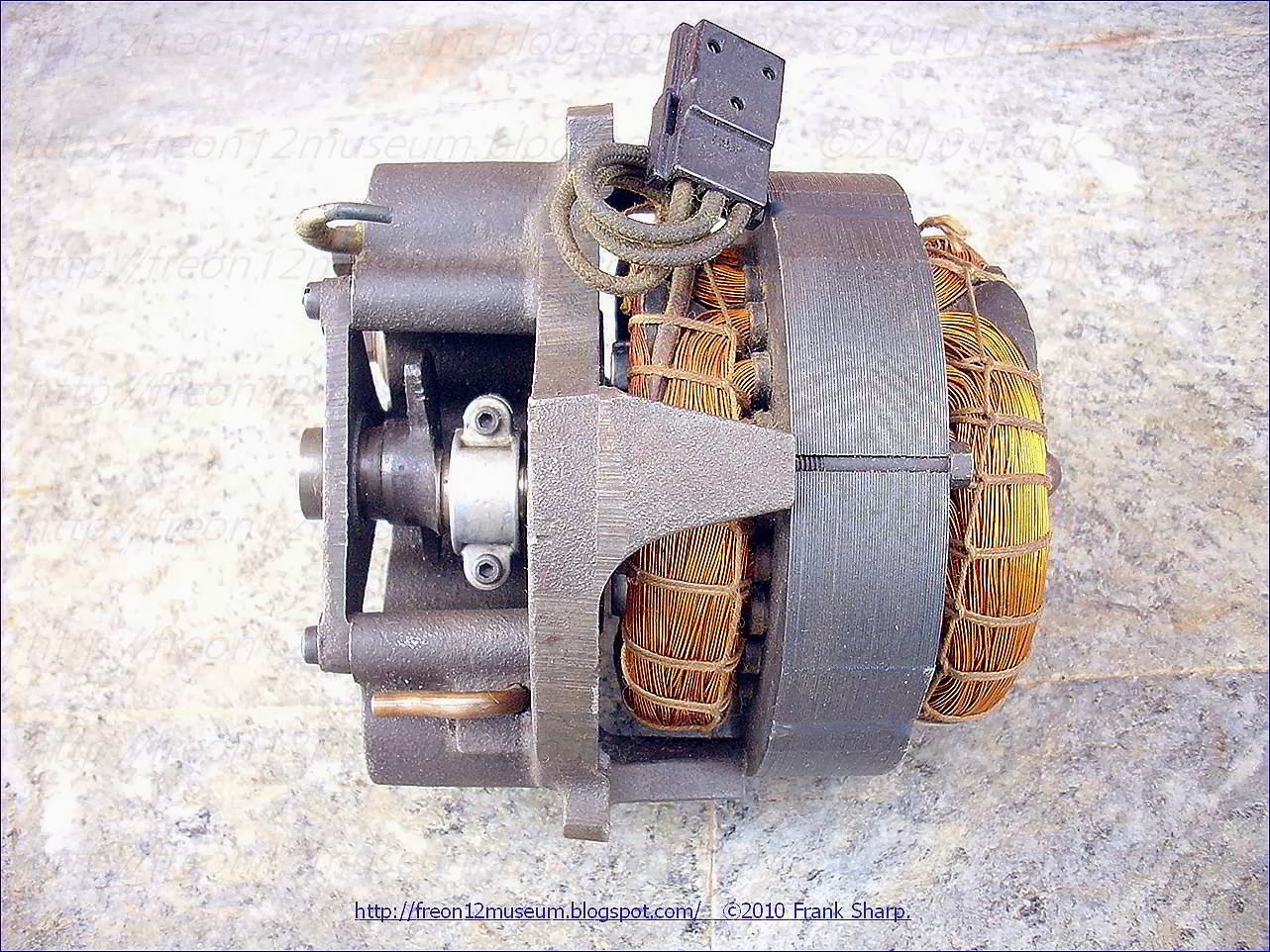
The PHILIPS (IGNIS) HN2126 was just scrapped by owner in the way as pictured, and in full perfect working order. I haven't cleaned or didn't anything.
It's a nice fridge PHILIPS branded but it's fabricated at the extint Italian
 IGNIS factory in the 60's.
The PHILIPS (IGNIS) HN2126 was first IGNIS refrigerator series fitted with polyurethane insulation system.
G.Borghi, IGNIS founder, was first Italian Appliances industry manager who discovered this insulation technology applied to fridge with the scope to obtain a smaller fridge cabinet without affecting the volumes of internal capacity.
G.Borghi, IGNIS founder, was first Italian Appliances industry manager who discovered this insulation technology applied to fridge with the scope to obtain a smaller fridge cabinet without affecting the volumes of internal capacity.
Furthemore He did a very smart reconsideration of his fridge prices combining capacity measures and final prices toghether.
It has excellent performance, it cools fast and deep in 30 minutes from initial warm state and it's super silent.
Many contemporary appliances would not have this level of staying power, many would ware out or require major services within just five years or less and of course, there is that perennial bug bear of planned obsolescence where components our deliberately designed to fail or manufactured with limited edition specificities..............................
It's very heavy because it has completely metal structure both external and internal (Enamel steel sheet) and is first PHILIPS / IGNIS refrigerator with a Polyurethane foam Insulation introduced by IGNIS first time instead of the classic hand-filled with mineral wood.
It's interesting how a fully functional nice refrigerator has served the first owner every day for almost 50 years without any issue and without saying a word. Then scrapped for.........What ???
This PHILIPS (IGNIS) HN2126 here in collection is ways more efficient and NICE than any modern cellular phone look fake expensive refrigerator ass crap build with eventually pentane crap insulation and with coils and other many things wich are self degrading to leak lets say in 3 / 5 yrs................And they're sold as...............................A++++++++.................!!!!!!!
Compressor Aspera Frigo (lic Tecumseh) AE12Z7 (12-211) 90W 72CAL/H INTERNAL VIEW:


Compressor Aspera Frigo (lic Tecumseh) AE12Z7 (12-211) 90W 72CAL/H HERMETIC COMPRESSOR Lubrication of sealed compressor:
Improved lubrication of sealed compressors having a crankshaft provided
with a longitudinal interior duct and a tubular member coupled to a
lower end of the interior duct and having a substantially cylindrical
upper section and a substantially conical lower section adapted to be
submerged in oil. An upper end of the internal lubrication duct ends in a
first substantially conical section and a second substantially
cylindrical section of variable contour depending upon the profile of
the upper end of the crankshaft. A spring may also be situated inside of
the tubular member.
1. In a sealed
compressor including a sealed casing in which an alternating
motor-driven compressor assembly is housed, the assembly including a
vertical-axis crankshaft provided with a longitudinal interior
lubrication duct communicating with points on an exterior surface of the
crankshaft and with an upper end of the same eccentrically to the axis
of rotation thereof, said assembly also including a tubular member
coupled to a lower end of said interior duct of the crankshaft and
comprising a substantially cylindrical upper section and a substantially
conical lower section adapted to be submerged in oil,
the improvement comprising
an upper end of said interior lubrication duct ending in a first substantially conical section and a second substantially cylindrical section of variable contour depending upon a profile of the upper end of the crankshaft, and
the profile of the upper end of the crankshaft cutting the duct at a transition point between the second substantially cylindrical section of variable contour and the first substantially conical section.
2. In a sealed compressor including a sealed casing in
which an alternating motor-driven compressor assembly is housed, the
assembly including a vertical-axis crankshaft provided with a
longitudinal interior lubrication duct communicating with points on an
exterior surface of the crankshaft and with an upper end of the same
eccentrically to the axis of rotation thereof, said assembly also
including a tubular member coupled to a lower end of said interior duct
of the crankshaft and comprising a substantially cylindrical upper
section and a substantially conical lower section adapted to be
submerged in oil,
the improvement comprising
an upper end of said interior lubrication duct ending in a first substantially conical section and a second substantially cylindrical section of a variable contour depending upon a profile of the upper end of the crankshaft,
a spring situated inside said tubular member,
wherein said spring is constituted by an elastic and resistant wire formed as a closed loop ending with a lower leg extending towards the lower substantially conical portion of the tubular member.
3. In a sealed compressor including a sealed casing in
which an alternating motor-driven compressor assembly is housed, the
assembly including a vertical-axis crankshaft provided with a
longitudinal interior lubrication duct communicating with points on a
exterior surface of the crankshaft and with an upper end of the same
eccentrically to the axis of rotation thereof, said assembly also
including a tubular member coupled to a lower end of said interior duct
of the crankshaft and comprising a substantially cylindrical upper
section and a substantially conical lower section adapted to be
submerged in oil,
the improvement comprising
an upper end of said interior lubrication duct ending in a first substantially conical section and a second substantially cylindrical section of variable contour depending upon a profile of the upper end of the crankshaft,
a spring situated inside said tubular member,
wherein said spring is constituted by an elastic and resistant wire shaped as a substantially inverted U with two arms and bent according to a profile of the lower conical section of the tubular member.
4. In a sealed compressor including a sealed casing in
which an alternating motor-driven compressor assembly is housed, the
assembly including a vertical-axis crankshaft provided with a
longitudinal interior lubrication duct communicating with points on an
exterior surface of the crankshaft and with an upper end of the same
eccentrically to the axis of rotation thereof, said assembly also
including a tubular member coupled to a lower end of said interior duct
of the crankshaft and comprising a substantially cylindrical upper
section and a substantially conical lower section adapted to be
submerged in oil,
the improvement comprising
an upper end of said interior lubrication duct ending in a first substantially conical section and a second substantially cylindrical section of variable contour depending upon a profile of the upper end of the crankshaft, and
a spring situated inside said tubular member,
wherein said spring is constituted by an elastic and resistant wire shaped substantially as a U with upper free ends joined together and a lower end shaped according to a profile of the lower conical section of the tubular member.
5. In a sealed compressor including a sealed casing in
which an alternating motor-driven compressor assembly is housed, the
assembly including a vertical-axis crankshaft provided with a
longitudinal interior lubrication duct communicating with points on an
exterior surface of the crankshaft and with an upper end of the same
eccentrically to the axis of rotation thereof, the assembly also
including a tubular member coupled to a lower end of the interior duct
of the crankshaft and comprising a substantially cylindrical upper
section and a substantially conical lower section adapted to be
submerged in oil,
the improvement comprising
a spring situated inside said tubular member,
wherein said spring is constituted by an elastic and resistant wire formed as a closed loop ending with a lower leg extending towards the lower substantially conical portion of the tubular member.
6. In a sealed compressor including a sealed casing in
which an alternating motor-drive compressor assembly is housed, the
assembly including a vertical-axis crankshaft provided with a
longitudinal interior lubrication duct communicating with points on an
exterior surface of the crankshaft and with an upper end of the same
eccentrically to the axis of rotation thereof, the assembly also
including a tubular member coupled to a lower end of the interior duct
of the crankshaft and comprising a substantially cylindrical upper
section and a substantially conical lower section adapted to be
submerged in oil,
the improvement comprising
a spring situated inside said tubular member,
wherein said spring is constituted by an elastic and resistant wire shaped as a substantially inverted U with two arms bent according to a profile of the lower conical section of the tubular member.
7. In a sealed compressor including a sealed casing in which an alternating motor-driven compressor assembly is housed, the assembly including a vertical-axis crankshaft provided with a longitudinal interior lubrication duct communicating with points on an exterior surface of the crankshaft and with an upper end of the same eccentrically to the axis of rotation thereof. the assembly also including a tubular member coupled to a lower end of the interior duct of the crankshaft and comprising a substantially cylindrical upper section and a substantially conical lower section adapted to be submerged in oil,
the improvement comprising
a spring situated inside said tubular member,
wherein said spring is constituted by an elastic and resistant wire shaped substantially as a U with upper free ends joined together and a lower end shaped according to a profile of the lower conical section of the tubular member.
the improvement comprising
an upper end of said interior lubrication duct ending in a first substantially conical section and a second substantially cylindrical section of variable contour depending upon a profile of the upper end of the crankshaft, and
the profile of the upper end of the crankshaft cutting the duct at a transition point between the second substantially cylindrical section of variable contour and the first substantially conical section.
the improvement comprising
an upper end of said interior lubrication duct ending in a first substantially conical section and a second substantially cylindrical section of a variable contour depending upon a profile of the upper end of the crankshaft,
a spring situated inside said tubular member,
wherein said spring is constituted by an elastic and resistant wire formed as a closed loop ending with a lower leg extending towards the lower substantially conical portion of the tubular member.
3. In a sealed compressor including a sealed casing in
which an alternating motor-driven compressor assembly is housed, the
assembly including a vertical-axis crankshaft provided with a
longitudinal interior lubrication duct communicating with points on a
exterior surface of the crankshaft and with an upper end of the same
eccentrically to the axis of rotation thereof, said assembly also
including a tubular member coupled to a lower end of said interior duct
of the crankshaft and comprising a substantially cylindrical upper
section and a substantially conical lower section adapted to be
submerged in oil, the improvement comprising
an upper end of said interior lubrication duct ending in a first substantially conical section and a second substantially cylindrical section of variable contour depending upon a profile of the upper end of the crankshaft,
a spring situated inside said tubular member,
wherein said spring is constituted by an elastic and resistant wire shaped as a substantially inverted U with two arms and bent according to a profile of the lower conical section of the tubular member.
4. In a sealed compressor including a sealed casing in
which an alternating motor-driven compressor assembly is housed, the
assembly including a vertical-axis crankshaft provided with a
longitudinal interior lubrication duct communicating with points on an
exterior surface of the crankshaft and with an upper end of the same
eccentrically to the axis of rotation thereof, said assembly also
including a tubular member coupled to a lower end of said interior duct
of the crankshaft and comprising a substantially cylindrical upper
section and a substantially conical lower section adapted to be
submerged in oil, the improvement comprising
an upper end of said interior lubrication duct ending in a first substantially conical section and a second substantially cylindrical section of variable contour depending upon a profile of the upper end of the crankshaft, and
a spring situated inside said tubular member,
wherein said spring is constituted by an elastic and resistant wire shaped substantially as a U with upper free ends joined together and a lower end shaped according to a profile of the lower conical section of the tubular member.
the improvement comprising
a spring situated inside said tubular member,
wherein said spring is constituted by an elastic and resistant wire formed as a closed loop ending with a lower leg extending towards the lower substantially conical portion of the tubular member.
6. In a sealed compressor including a sealed casing in
which an alternating motor-drive compressor assembly is housed, the
assembly including a vertical-axis crankshaft provided with a
longitudinal interior lubrication duct communicating with points on an
exterior surface of the crankshaft and with an upper end of the same
eccentrically to the axis of rotation thereof, the assembly also
including a tubular member coupled to a lower end of the interior duct
of the crankshaft and comprising a substantially cylindrical upper
section and a substantially conical lower section adapted to be
submerged in oil, the improvement comprising
a spring situated inside said tubular member,
wherein said spring is constituted by an elastic and resistant wire shaped as a substantially inverted U with two arms bent according to a profile of the lower conical section of the tubular member.
7. In a sealed compressor including a sealed casing in which an alternating motor-driven compressor assembly is housed, the assembly including a vertical-axis crankshaft provided with a longitudinal interior lubrication duct communicating with points on an exterior surface of the crankshaft and with an upper end of the same eccentrically to the axis of rotation thereof. the assembly also including a tubular member coupled to a lower end of the interior duct of the crankshaft and comprising a substantially cylindrical upper section and a substantially conical lower section adapted to be submerged in oil,
the improvement comprising
a spring situated inside said tubular member,
wherein said spring is constituted by an elastic and resistant wire shaped substantially as a U with upper free ends joined together and a lower end shaped according to a profile of the lower conical section of the tubular member.
Description:
BACKGROUND OF THE INVENTION
The present invention relates to improvements in the lubrication system of sealed compressors for cooling fluids.
Sealed compressors for cooling fluids are known which include a sealed casing with an alternating motor-driven compressor assembly housed in the interior thereof, the assembly including a vertical-axis crankshaft provided with a longitudinal interior lubrication duct communicating with various points on the exterior surface of the crankshaft and with an upper end of the same, eccentrically to the axis of rotation thereof. The assembly also includes a tubular device coupled to a lower end of the interior duct of the crankshaft, such tubular device having a first upper section substantially cylindrical and a second substantially conical section with an end having an orifice for the introduction of oil.
In such compressors, the oiling of the parts that are in friction is accomplished by means of the oil fluid supplied by the tubular device, which, when rotating and immersed in an oil mass, produces by centrifugal force the raising of the oil through the interior duct of the crankshaft towards the oiling points of the mechanism. Part of the oil exits out of the eccentric orifice at the upper end of the crankshaft, propelled against the interior surface of the sealed casing of the compressor.
There are various patents that disclose particular details of this oiling or lubricating system. U.S. Pat. No. 3,410,478 discloses a cylindrical tubular device joined by a conical section, as well as a wall placed in the interior of the tubular device acting as a gate, such a wall being costly to construct. U.S. Pat. No. 3,451,615 discloses a lateral outflow passage from an eccentric upper section of the interior duct of the crankshaft.
Lastly, Spanish Patent No. 504,039 discloses a channel in the extreme upper face of the crankshaft, arguing the lower cost of constructing such a channel in relation to the lateral outflow passage disclosed in the aforementioned U.S. Pat. No. 3,451,615.
It has been possible to confirm that the current solutions of tubular pumping devices lose part of their effectiveness as the compressor's operating temperature rises. Under these conditions, the fluidity of the oil mass deposited in the housing of the compressor reaches a point such that the oil mass loses velocity of rotation in relation to the velocity of rotation of the tubular device. Such device loses effectiveness as a centrifugal pump due to sliding between the interior wall of the tubular device and the layer of oil in contact with the wall.
The aforementioned interior wall that acts as a gate may, in part, solve the problem described, but it has the drawback of having a high cost of construction. Moreover, the orifice at the upper end of the crankshaft should have a certain form, so that the oil that exits therefrom has sufficient force to be propelled against the interior wall of the sealed casing of the compressor. This certain form, in the compressors that are known, entails significant difficulties in construction.
SUMMARY OF THE INVENTION
With the improvements of the invention, the noted drawbacks can be eliminated.
Accordingly, it is an object of the present invention to eliminate the drawbacks noted above with respect to the prior art.
It is also an object of the present invention to simplify the lubrication of compressors.
It is another object of the present invention to lower manufacturing cost of a lubrication system for compressors.
It is a further object of the present invention to compensate for the decrease in oil viscosity caused by a rise in temperature in the lubrication system of a compressor.
These and other objects are attained by the present invention which is directed to improvements in the lubrication system of compressors for cooling fluids. According to the present invention, the upper end of the interior lubrication duct in a crankshaft of the compressor ends in a first substantially conical section and a second substantially cylindrical section of variable contour depending upon the profile of the upper end of the crankshaft. This distinct configuration of the upper end of the lubrication duct offers the advantage of greater simplicity in construction and consequently a lower manufacturing cost, while at the same time maintaining the same efficiency as other current forms of more complicated configuration.
Advantageously, the tubular device, which is coupled to the lower end of the interior duct of the crankshaft, is provided in its interior with a spring formed by an elastic and resistant wire affixed by means of pressure and by insertion of a part of the spring in a substantially conical section of the tubular device or member submerged in oil (the tubular device comprises a first substantially cylindrical upper section and a second substantially conical lower section adapted to be inserted into oil). The part of the spring submerged in the oil acts as a paddle propelling the oil, and thereby compensating for decrease in oil viscosity caused by the temperature.
The aforementioned spring may have various
forms or structures in accordance with the present invention. In one
embodiment, the spring forms a closed loop which ends with a lower leg
thereof extending towards the lower substantially conical portion of the
tubular device or member. In a second embodiment, the spring takes the
form of two arms making a substantially inverted U, and bent according
to the conical profile of the tubular device. In another embodiment, the
spring takes the form of two arms shaped in a U and bent according to
the conical profile of the tubular device and with the free ends thereof
joined at the upper portion thereof.
All the noted spring shapes may be constructed with wire having a circular or a square cross-section so as to improve the attachment thereof within the interior of the tubular device or member.
BRIEF DESCRIPTION OF THE DRAWINGS
For a fuller understanding thereof, the present invention will be described in greater detail below with reference to the accompanying drawings in which certain embodiments of the present invention are schematically illustrated and to which the present invention is not intended to be exclusively restricted.
In the drawings,
FIG. 1 illustrates a longitudinal sectional view of a sealed compressor of cooling fluids, in which the improvements according to the present invention are applied;
FIG. 2 is a partially sectional side view of a crank shaft and of a tubular device having the improvements according to the present invention; and
FIGS. 3 and 4 each illustrate springs for the tubular device illustrated in FIG. 2.

DESCRIPTION OF THE PREFERRED EMBODIMENTS
Referring to FIG. 1, a compressor 1 includes a sealed casing 2 with an alternating motor-driven compressor assembly housed in the interior thereof, the assembly including a vertical-axis crankshaft 3 provided with a longitudinal interior lubrication duct 4 (FIG. 2) communicating with various points 5,6 on the exterior surface of the crankshaft 3, and with the upper end 7 of the same, eccentrically to the axis of rotation thereof. The assembly also includes a tubular device 8 coupled to a lower end of the interior duct 4 of the crankshaft 3, the tubular device 8 comprising a first upper section 9 that is substantially cylindrical and a second lower substantially conical section 10 to be submerged in oil.
As can be seen in FIG. 2, the upper end 7 of the lubrication duct 4 terminates in a first substantially conical section 11 and a second substantially cylindrical section 12 of variable contour depending upon the profile 13 of the upper end 7 of the crankshaft 3.
As also illustrated in FIG. 2, the tubular device 8 is provided in the interior with a spring 14 formed by an elastic and resistant wire, e.g. of tempered steel, and affixed by means of pressure and by insertion of part of the spring in the conical section 10 of the tubular device or member 8 which is adapted to be submerged in the oil. As shown in FIG. 2, the spring 14 takes the form of two arms 15 and 16 shaped into an inverted U and bent at points 17 and 18 according to the conical profile of the tubular device or member 8.
In FIG. 3, the spring 14 forms a closed loop 19 ending with a lower leg 20 thereof extending towards the lower conical part 10 of the tubular device 8.

The spring illustrated in FIG. 4 takes the form of two arms 21 and 22 in the shape of a U bent at points 23 and 24 according to the conical profile of the tubular device 8 (i.e. the lower substantially conical section 10 thereof) and with the free ends 25 and 26 thereof joined at the upper portion as illustrated.
As described above, the springs are introduced into the tubular device 8 with the lower portion thereof situated in the conical section 10 to be submerged in oil. When the crankshaft 3 rotates, driven by the rotor of the electrical motor, the tubular device 8 rotates along with spring 14, with the lower part of the spring submerged in oil acting as a paddle.
The characteristic form 11 of the outflow orifice in the upper end 7 of the lubrication duct 4 permits the oil that flows through the eccentric duct 4 to be propelled in a continuous jet against the interior wall of the casing 2.
It follows from the description above that the improvements according to the present invention allow for enhancement in the lubrication of the crankshaft and in the propulsion of oil against the interior wall of the casing 2 due to the springs 14 acting as paddles, and allows for a reduction in the cost of manufacture of the crankshaft 3 by simplifying the orifice at the upper end 7 of the crankshaft 3 without diminishing the effectiveness thereof. Similarly, the cost of construction of the spring 14 is much lower than the previously described interior wall with respect to the prior art.
The preceding description of the present invention is merely exemplary, and is not intended to limit the scope thereof in any way.
The present invention relates to improvements in the lubrication system of sealed compressors for cooling fluids. Sealed compressors for cooling fluids are known which include a sealed casing with an alternating motor-driven compressor assembly housed in the interior thereof, the assembly including a vertical-axis crankshaft provided with a longitudinal interior lubrication duct communicating with various points on the exterior surface of the crankshaft and with an upper end of the same, eccentrically to the axis of rotation thereof. The assembly also includes a tubular device coupled to a lower end of the interior duct of the crankshaft, such tubular device having a first upper section substantially cylindrical and a second substantially conical section with an end having an orifice for the introduction of oil.
In such compressors, the oiling of the parts that are in friction is accomplished by means of the oil fluid supplied by the tubular device, which, when rotating and immersed in an oil mass, produces by centrifugal force the raising of the oil through the interior duct of the crankshaft towards the oiling points of the mechanism. Part of the oil exits out of the eccentric orifice at the upper end of the crankshaft, propelled against the interior surface of the sealed casing of the compressor.
There are various patents that disclose particular details of this oiling or lubricating system. U.S. Pat. No. 3,410,478 discloses a cylindrical tubular device joined by a conical section, as well as a wall placed in the interior of the tubular device acting as a gate, such a wall being costly to construct. U.S. Pat. No. 3,451,615 discloses a lateral outflow passage from an eccentric upper section of the interior duct of the crankshaft.
Lastly, Spanish Patent No. 504,039 discloses a channel in the extreme upper face of the crankshaft, arguing the lower cost of constructing such a channel in relation to the lateral outflow passage disclosed in the aforementioned U.S. Pat. No. 3,451,615.
It has been possible to confirm that the current solutions of tubular pumping devices lose part of their effectiveness as the compressor's operating temperature rises. Under these conditions, the fluidity of the oil mass deposited in the housing of the compressor reaches a point such that the oil mass loses velocity of rotation in relation to the velocity of rotation of the tubular device. Such device loses effectiveness as a centrifugal pump due to sliding between the interior wall of the tubular device and the layer of oil in contact with the wall.
The aforementioned interior wall that acts as a gate may, in part, solve the problem described, but it has the drawback of having a high cost of construction. Moreover, the orifice at the upper end of the crankshaft should have a certain form, so that the oil that exits therefrom has sufficient force to be propelled against the interior wall of the sealed casing of the compressor. This certain form, in the compressors that are known, entails significant difficulties in construction.
SUMMARY OF THE INVENTION
With the improvements of the invention, the noted drawbacks can be eliminated.
Accordingly, it is an object of the present invention to eliminate the drawbacks noted above with respect to the prior art. It is also an object of the present invention to simplify the lubrication of compressors.
It is another object of the present invention to lower manufacturing cost of a lubrication system for compressors.
It is a further object of the present invention to compensate for the decrease in oil viscosity caused by a rise in temperature in the lubrication system of a compressor.
These and other objects are attained by the present invention which is directed to improvements in the lubrication system of compressors for cooling fluids. According to the present invention, the upper end of the interior lubrication duct in a crankshaft of the compressor ends in a first substantially conical section and a second substantially cylindrical section of variable contour depending upon the profile of the upper end of the crankshaft. This distinct configuration of the upper end of the lubrication duct offers the advantage of greater simplicity in construction and consequently a lower manufacturing cost, while at the same time maintaining the same efficiency as other current forms of more complicated configuration.
Advantageously, the tubular device, which is coupled to the lower end of the interior duct of the crankshaft, is provided in its interior with a spring formed by an elastic and resistant wire affixed by means of pressure and by insertion of a part of the spring in a substantially conical section of the tubular device or member submerged in oil (the tubular device comprises a first substantially cylindrical upper section and a second substantially conical lower section adapted to be inserted into oil). The part of the spring submerged in the oil acts as a paddle propelling the oil, and thereby compensating for decrease in oil viscosity caused by the temperature.
All the noted spring shapes may be constructed with wire having a circular or a square cross-section so as to improve the attachment thereof within the interior of the tubular device or member.
BRIEF DESCRIPTION OF THE DRAWINGS
For a fuller understanding thereof, the present invention will be described in greater detail below with reference to the accompanying drawings in which certain embodiments of the present invention are schematically illustrated and to which the present invention is not intended to be exclusively restricted.
In the drawings,
FIG. 1 illustrates a longitudinal sectional view of a sealed compressor of cooling fluids, in which the improvements according to the present invention are applied;
FIG. 2 is a partially sectional side view of a crank shaft and of a tubular device having the improvements according to the present invention; and
FIGS. 3 and 4 each illustrate springs for the tubular device illustrated in FIG. 2.

DESCRIPTION OF THE PREFERRED EMBODIMENTS
Referring to FIG. 1, a compressor 1 includes a sealed casing 2 with an alternating motor-driven compressor assembly housed in the interior thereof, the assembly including a vertical-axis crankshaft 3 provided with a longitudinal interior lubrication duct 4 (FIG. 2) communicating with various points 5,6 on the exterior surface of the crankshaft 3, and with the upper end 7 of the same, eccentrically to the axis of rotation thereof. The assembly also includes a tubular device 8 coupled to a lower end of the interior duct 4 of the crankshaft 3, the tubular device 8 comprising a first upper section 9 that is substantially cylindrical and a second lower substantially conical section 10 to be submerged in oil.
As can be seen in FIG. 2, the upper end 7 of the lubrication duct 4 terminates in a first substantially conical section 11 and a second substantially cylindrical section 12 of variable contour depending upon the profile 13 of the upper end 7 of the crankshaft 3.
As also illustrated in FIG. 2, the tubular device 8 is provided in the interior with a spring 14 formed by an elastic and resistant wire, e.g. of tempered steel, and affixed by means of pressure and by insertion of part of the spring in the conical section 10 of the tubular device or member 8 which is adapted to be submerged in the oil. As shown in FIG. 2, the spring 14 takes the form of two arms 15 and 16 shaped into an inverted U and bent at points 17 and 18 according to the conical profile of the tubular device or member 8.
In FIG. 3, the spring 14 forms a closed loop 19 ending with a lower leg 20 thereof extending towards the lower conical part 10 of the tubular device 8.

The spring illustrated in FIG. 4 takes the form of two arms 21 and 22 in the shape of a U bent at points 23 and 24 according to the conical profile of the tubular device 8 (i.e. the lower substantially conical section 10 thereof) and with the free ends 25 and 26 thereof joined at the upper portion as illustrated.
As described above, the springs are introduced into the tubular device 8 with the lower portion thereof situated in the conical section 10 to be submerged in oil. When the crankshaft 3 rotates, driven by the rotor of the electrical motor, the tubular device 8 rotates along with spring 14, with the lower part of the spring submerged in oil acting as a paddle.
The characteristic form 11 of the outflow orifice in the upper end 7 of the lubrication duct 4 permits the oil that flows through the eccentric duct 4 to be propelled in a continuous jet against the interior wall of the casing 2.
It follows from the description above that the improvements according to the present invention allow for enhancement in the lubrication of the crankshaft and in the propulsion of oil against the interior wall of the casing 2 due to the springs 14 acting as paddles, and allows for a reduction in the cost of manufacture of the crankshaft 3 by simplifying the orifice at the upper end 7 of the crankshaft 3 without diminishing the effectiveness thereof. Similarly, the cost of construction of the spring 14 is much lower than the previously described interior wall with respect to the prior art.
The preceding description of the present invention is merely exemplary, and is not intended to limit the scope thereof in any way.
IGNIS, GIOVANNI BORGHI HISTORY.
Investing in the industrial development of artisan villages
in Varese, Italy, Giovanni Borghi builds a factory for 200
employees to manufacture not only ovens and cooktops, but
also an appliance previously unknown in Italy: the refrigerator.
Ignis workers produce appliances for third-party companies
like Fiat, Atlantic, Philco, Emerson and Philips. Borghi builds
the “Villages of Ignis,” with affordable one- and two-family
houses (Borghi Villages), as well as a pool and sports center
in Comerio, Italy, and a hostel vvith recreational facilities for
young workers in Cassinetta, Italy, all intended to promote a
comfortable, healthy lifestyle.
in Varese, Italy, Giovanni Borghi builds a factory for 200
employees to manufacture not only ovens and cooktops, but
also an appliance previously unknown in Italy: the refrigerator.
Ignis workers produce appliances for third-party companies
like Fiat, Atlantic, Philco, Emerson and Philips. Borghi builds
the “Villages of Ignis,” with affordable one- and two-family
houses (Borghi Villages), as well as a pool and sports center
in Comerio, Italy, and a hostel vvith recreational facilities for
young workers in Cassinetta, Italy, all intended to promote a
comfortable, healthy lifestyle.
 The Milan industrialist Giovanni Borghi founded
the IGNIS brand of household appliances. His factories would turn out
one appliance every eight seconds, and make billions selling them to
Italy's exploding middle class. Borghi was famous for his early
support of cycling, and his yellow IGNIS jerseyed squadra won more than a
few great races in the late fifties and early sixties.
The Milan industrialist Giovanni Borghi founded
the IGNIS brand of household appliances. His factories would turn out
one appliance every eight seconds, and make billions selling them to
Italy's exploding middle class. Borghi was famous for his early
support of cycling, and his yellow IGNIS jerseyed squadra won more than a
few great races in the late fifties and early sixties.Borghi was aggressive, flamboyant and flashy. And he took care of his stars - famously buying Spanish sprinter Miguel Poblet a Lancia convertible after his Milan San Remo win. On top of his 25 million lire per year salary.
Giovanni
Borghi, was an Italian industrialist pioneer in the field of domestic
appliances, returned from a trip in the USA with a real
illumination: refrigerators insulated with Polyurethane foam were much more
efficient and capacious than those hand-filled with mineral wood.
His refrigerators Group, Ignis, developed internally this technology and the
related equipment, a suitable alternative to the imported foam dispensers, which
were difficult to get, fix and maintain, stimulating an industrial supply of
similar machines.
illumination: refrigerators insulated with Polyurethane foam were much more
efficient and capacious than those hand-filled with mineral wood.
His refrigerators Group, Ignis, developed internally this technology and the
related equipment, a suitable alternative to the imported foam dispensers, which
were difficult to get, fix and maintain, stimulating an industrial supply of
similar machines.

Borghi kept control of IGNIS in the family. In the paternalistic Italian industrial model - like Ferrari, Maserati or Campagnolo. He later turned the reins over to his son, who in turn finally sold the company to Dutch conglomerate, Philips.
When Philips decided to get into the major household appliances
market, its procedure was to buy increasing quantities of these goods from the Italian firm, Ignis, then at the height of its prosperity.
Once it became the principal client of the manufacturer, it took over supplying the latter by purchasing 50 percent of its capital. It took over the firm completely in 1972, to the satisfaction of the founder of Ignis, Giovanni Borghi.
BORGHI DIED IN 1975.
Borghi is still remembered in Italia. RAI even aired TV miniseries about his life this past year, "Mister Ignis".
Koninklijke Philips Electronics N.V. (Royal Philips Electronics Inc.), most commonly known as Philips, (Euronext: PHIA, NYSE: PHG) is a multinational Dutch electronics corporation.
Philips is one of the largest electronics companies in the world. In 2009, its sales were €23.18 billion. The company employs 115,924 people in more than 60 countries.[1]
Philips is organized in a number of sectors: Philips Consumer Lifestyles (formerly Philips Consumer Electronics and Philips Domestic Appliances and Personal Care), Philips Lighting and Philips Healthcare (formerly Philips Medical Systems).
The company was founded in 1891 by Gerard Philips, a maternal cousin of Karl Marx, in Eindhoven, Netherlands. Its first products were light bulbs and other electro-technical equipment. Its first factory survives as a museum devoted to light sculpture.[2] In the 1920s, the company started to manufacture other products, such as vacuum tubes (also known worldwide as 'valves'), In 1927 they acquired the British electronic valve manufacturers Mullard and in 1932 the German tube manufacturer Valvo, both of which became subsidiaries. In 1939 they introduced their electric razor, the Philishave (marketed in the USA using the Norelco brand name).

Philips was also instrumental in the revival of the Stirling engine.
As a chip maker, Philips Semiconductors was among the Worldwide Top 20 Semiconductor Sales Leaders.
In December 2005 Philips announced its intention to make the Semiconductor Division into a separate legal entity. This process of "disentanglement" was completed on 1 October 2006.
On 2 August 2006, Philips completed an agreement to sell a controlling 80.1% stake in Philips Semiconductors to a consortium of private equity investors consisting of Kohlberg Kravis Roberts & Co. (KKR), Silver Lake Partners and AlpInvest Partners. The sale completed a process, which began December 2005, with its decision to create a separate legal entity for Semiconductors and to pursue all strategic options. Six weeks before, ahead of its online dialogue, through a letter to 8,000 of Philips managers, it was announced that they were speeding up the transformation of Semiconductors into a stand-alone entity with majority ownership by a third party. It was stated then that "this is much more than just a transaction: it is probably the most significant milestone on a long journey of change for Philips and the beginning of a new chapter for everyone – especially those involved with Semiconductors".
In its more than 115 year history, this co
 unts
as a big step that is definitely changing the profile of the
company. Philips was one of few companies that successfully made the
transition from the electrical world of the 19th century into the
electronic age, starting its semiconductor activity in 1953 and
building it into a global top 10 player in its industry. As such,
Semiconductors was at the heart of many innovations in Philips over
the past 50 years.
unts
as a big step that is definitely changing the profile of the
company. Philips was one of few companies that successfully made the
transition from the electrical world of the 19th century into the
electronic age, starting its semiconductor activity in 1953 and
building it into a global top 10 player in its industry. As such,
Semiconductors was at the heart of many innovations in Philips over
the past 50 years.Agreeing to start a process that would ultimately lead to the decision to sell the Semiconductor Division therefore was one of the toughest decisions that the Board of Management ever had to make.
On 21 August 2006, Bain Capital and Apax Partners announced that they had signed definitive commitments to join the expanded consortium headed by KKR that is to acquire the controlling stake in the Semiconductors Division.
On 1 September 2006, it was announced in Berlin that the name of the new semiconductor company founded by Philips is NXP Semiconductors.
Coinciding with the sale of the Semiconductor Division, Philips also announced that they would drop the word 'Electronics' from the company name, thus becoming simply Koninklijke Philips N.V. (Royal Philips N.V.).
PHILIPS FOUNDATION:
 The
foundations of Philips were laid in 1891 when Anton and Gerard
Philips established Philips & Co. in Eindhoven, the
Netherlands. The company begun manufacturing carbon-filament lamps
and by the turn of the century, had become one of the largest
producers in Europe. Stimulated by the industrial revolution in
Europe, Philips’ first research laboratory started introducing its
first innovations in the x-ray and radio technology. Over the years,
the list of inventions has only been growing to include many
breakthroughs that have continued to enrich people’s everyday lives.
The
foundations of Philips were laid in 1891 when Anton and Gerard
Philips established Philips & Co. in Eindhoven, the
Netherlands. The company begun manufacturing carbon-filament lamps
and by the turn of the century, had become one of the largest
producers in Europe. Stimulated by the industrial revolution in
Europe, Philips’ first research laboratory started introducing its
first innovations in the x-ray and radio technology. Over the years,
the list of inventions has only been growing to include many
breakthroughs that have continued to enrich people’s everyday lives.In the early years of Philips & Co., the representation of the company name took many forms: one was an emblem formed by the initial letters of Philips & Co., and another was the word Philips printed on the glass of metal filament lamps.
One of the very first campaigns was launched in 1898 when Anton Philips used a range of postcards showing the Dutch national costumes as marketing tools. Each letter of the word Philips was printed in a row of light bulbs as at the top of every card. In the late 1920s, the Philips name began to take on the form that we recognize today.
The now familiar Philips waves and stars first appeared in 1926 on the packaging of miniwatt radio valves, as well as on the Philigraph, an early sound recording device. The waves symbolized radio waves, while the stars represented the ether of the evening sky through which the radio waves would travel.
In 1930 it was the first time that the four stars flanking the three waves were placed together in a circle. After that, the
stars and waves started appearing on radios and gramophones,
featuring this circle as part of their design. Gradually the use of
the circle emblem was then extended to advertising materials and other
products.At this time Philips’ business activities were expanding rapidly and the company wanted to find a trademark that would uniquely represent Philips, but one that would also avoid legal problems with the owners of other well-known circular emblems. This wish resulted in the combination of the Philips circle and the wordmark within the shield emblem.
In 1938, the Philips shield made its first appearance. Although modified over the years, the basic design has remained constant ever since and, together with the wordmark, gives Philips the distinctive identity that is still embraced today.
Gerard Philips:
 Gerard
Leonard Frederik Philips (October 9, 1858, in Zaltbommel – January
27, 1942, in The Hague, Netherlands) was a Dutch industrialist,
co-founder (with his father Frederik Philips) of the Philips Company
as a family business in 1891. Gerard and his younger brother Anton
Philips changed the business to a corporation by founding in 1912 the
NV Philips' Gloeilampenfabrieken. As the first CEO of the Philips
corporation, Gerard laid with Anton the base for the later Philips
multinational.
Gerard
Leonard Frederik Philips (October 9, 1858, in Zaltbommel – January
27, 1942, in The Hague, Netherlands) was a Dutch industrialist,
co-founder (with his father Frederik Philips) of the Philips Company
as a family business in 1891. Gerard and his younger brother Anton
Philips changed the business to a corporation by founding in 1912 the
NV Philips' Gloeilampenfabrieken. As the first CEO of the Philips
corporation, Gerard laid with Anton the base for the later Philips
multinational.Early life and education
Gerard was the first son of Benjamin Frederik David Philips (1 December 1830 – 12 June 1900) and Maria Heyligers (1836 – 1921). His father was active in the tobacco business and a banker at Zaltbommel in the Netherlands; he was a first cousin of Karl Marx.
Career
Gerard Philips became interested in electronics and engineering. Frederik was the financier for Gerard's purchase of the old factory building in Eindhoven where he established the first factory in 1891. They operated the Philips Company as a family business for more than a decade.
Marriage and family
On March 19, 1896 Philips married Johanna van der Willigen (30 September 1862 – 1942). They had no children.
Gerard was an uncle of Frits Philips, whom he and his brother brought into the business. Later they brought in his brother's grandson, Franz Otten.
Gerard and his brother Anton supported education and social programs in Eindhoven, including the Philips Sport Vereniging (Philips Sports Association), which they founded. From it the professional football (soccer) department developed into the independent Philips Sport Vereniging N.V.
Anton Philips:
 Anton
Frederik Philips (March 14, 1874, Zaltbommel, Gelderland – October
7, 1951, Eindhoven) co-founded Royal Philips Electronics N.V. in 1912
with his older brother Gerard Philips in Eindhoven, the Netherlands.
He served as CEO of the company from 1922 to 1939.
Anton
Frederik Philips (March 14, 1874, Zaltbommel, Gelderland – October
7, 1951, Eindhoven) co-founded Royal Philips Electronics N.V. in 1912
with his older brother Gerard Philips in Eindhoven, the Netherlands.
He served as CEO of the company from 1922 to 1939.Early life and education
Anton was born to Maria Heyligers (1836 – 1921) and Benjamin Frederik David Philips (December 1, 1830 – June 12, 1900). His father was active in the tobacco business and a banker at Zaltbommel in the Netherlands. (He was a first cousin to Karl Marx.) Anton's brother Gerard was 16 years older.
Career
In May 1891 the father Frederik was the financier and, with his son Gerard Philips, co-founder of the Philips Company as a family business. In 1912 Anton joined the firm, which they named Royal Philips Electronics N.V.
During World War I, Anton Philips managed to increas
e
sales by taking advantage of a boycott of German goods in several
countries. He provided the markets with alternative products.Anton (and his brother Gerard) are remembered as being civic-minded. In Eindhoven they supported education and social programs and facilities, such as the soccer department of the Philips Sports Association as the best-known example.
Anton Philips brought his son Frits Philips and grandson Franz Otten into the company in their times. Anton took the young Franz Otten with him and other family members to escape the Netherlands just before the Nazi Occupation during World War II; they went to the United States. They returned after the war.
His son Frits Philips chose to stay and manage the company during the occupation; he survived several months at the concentration camp of Vught after his workers went on strike. He saved the lives of 382 Jews by claiming them as indispensable to his factory, and thus helped them evade Nazi roundups and deportation to concentration camps.
Philips died in Eindhoven in 1951.
Marriage and family
Philips married Anne Henriëtte Elisabeth Maria de Jongh (Amersfoort, May 30, 1878 – Eindhoven, March 7, 1970). They had the following children:
* Anna Elisabeth Cornelia Philips (June 19, 1899 – ?), married in 1925 to Pieter Franciscus Sylvester Otten (1895 – 1969), and had:
o Diek Otten
o Franz Otten (b. c. 1928 - d. 1967), manager in the Dutch electronics company Philips
* Frederik Jacques Philips (1905-2005)
* Henriëtte Anna Philips (Eindhoven, October 26, 1906 – ?), married firstly to A. Knappert (d. 1932), without issue; married secondly to G. Jonkheer Sandberg (d. September 5, 1935), without issue; and married thirdly in New York City, New York, on September 29, 1938 to Jonkheer Gerrit van Riemsdijk (Aerdenhout, January 10, 1911 – Eindhoven, November 8, 2005). They had the following children:
o ..., Jonkheerin Gerrit van Riemsdijk (b. Waalre, October 2, 1939), married at Waalre on February 17, 1968 to Johannes Jasper Tuijt (b. Atjeh, Koeta Radja, March 10, 1930), son of Jacobus Tuijt and wife Hedwig Jager, without issue
o ..., Jonkheerin Gerrit van Riemsdijk (b. Waalre, April 3, 1946), married firstly at Calvados, Falaise, on June 6, 1974 to Martinus Jan Petrus Vermooten (Utrecht, September 16, 1939 – Falaise, August 29, 1978), son of Martinus Vermooten and wife Anna Pieternella Hendrika Kwantes, without issue; married secondly in Paris on December 12, 1981 to Jean Yves Louis Bedos (Calvados, Rémy, January 9, 1947 – Calvados, Lisieux, October 5, 1982), son of Georges Charles Bedos and wife Henriette Louise Piel, without issue; and married thirdly at Manche, Sartilly, on September 21, 1985 to Arnaud Evain (b. Ardennes, Sedan, July 7, 1952), son of Jean Claude Evain and wife Flore Halleux, without issue
o ..., Jonkheerin Gerrit van Riemsdijk (b. Waalre, September 4, 1948), married at Waalre, October 28, 1972 to Elie Johan François van Dissel (b. Eindhoven, October 9, 1948), son of Willem Pieter
Jacob van Dissel and wife Francisca Frederike Marie Wirtz, without issue.
Tecumseh products Company HISTORY:It was Incorporated in 1930 as Hillsdale Machine & Tool Company, All Other Plastics Product Manufacturing; Air-Conditioning and Warm Air Heating Equipment and Commercial and Industrial Refrigeration Equipment Manufacturing; Other Engine Equipment Manufacturing; Speed Changer, Industrial High-Speed Drive, and Gear Manufacturing; Pump and Pumping Equipment Manufacturing; Motor and Generator Manufacturing; Gasoline Engine and Engine Parts Manufacturing, Named for the legendary Shawnee chief, Tecumseh Products makes a line of hermetically sealed compressors and heat pumps for residential and commercial refrigerators and freezers, water coolers, air conditioners, dehumidifiers, and vending machines. The company's line of scroll compressor models are suited for demanding commercial refrigeration applications and consist primarily of reciprocating and rotary designs. Tecumseh sells its products to OEMs and aftermarket distributors in more than 100 countries worldwide, with 80% of its sales generated outside of the US. It markets its products under brand names that include Celseon, L'Unité Hermétique, Masterflux, Silensys, and Vector.
Tecumseh Products Company manufactures compressors for refrigeration and air conditioning equipment, gasoline engines and automobile transmissions, and pumps and pumping equipment for industrial, commercial, and agricultural use. The second largest domestic manufacturer of engines for small tractors, snow blowers, and lawn mowers, the company is best known for its compressors, machines that compress refrigerants in air conditioners and refrigerators. The town of Tecumseh, Michigan, in which the company is headquartered, has since become known as the "Refrigeration Capital of the World."
An early 1990s public offering brought in new capital while allowing the founding Herrick family to retain control. The company has since moved to establish manufacturing hubs in Brazil and India while cutting back on U.S. production. Tecumseh has acquired some suppliers and is attempting to make its brand more visible to consumers and contractors.
Tecumseh Products was founded by Ray W. Herrick, a master toolmaker who came to prominence in the 1920s in Michigan's growing auto industry. Herrick's reputation as a knowledgeable and highly skilled toolmaker led to his rapid advancement in the industry. He was given supervisory positions and became a friend and adviser to influential inventors and industrialists such as Henry Ford, Harvey Firestone, and Thomas Edison. In 1928 Herrick was asked to help turn around the struggling Alamo Engine Company in the southeastern Michigan town of Hillsdale, where he served until 1933 as factory manager and eventually as director of sales and production. The company continued to decline, however, and during this time Herrick and a local toolmaker named C.F. (Bill) Sage decided to launch a business of their own, incorporating as Hillsdale Machine & Tool Company in 1930.
The Hillsdale company manufactured high-quality automobile and electric refrigerator parts, as well as small tools and mechanical novelties. Also handling orders that Alamo could not fill, the Hillsdale company went from grossing $26,000 in sales during its first year of operation to $284,000 by 1933. Initially, two-thirds of the company's stock was owned by Sage and his wife, while Herrick owned the remaining third. By 1933, however, Herrick bought out most of their interest and gained control of the company.
Competition in the manufactured parts industry was fierce in 1933, and Hillsdale soon sought larger production facilities. When Alamo went into receivership that year, Herrick leased its plant for one year, hoping to purchase it at the end of the term. The rent paid to Alamo's receivers, however, cut into the Hillsd
ale company's profits. Furthermore, the Hillsdale company had been founded during the height of the Great Depression, and these early years were characterized by escalating debt and inadequate cash flow. By 1934, Herrick's company was close to bankruptcy.That year, however, as a result of a concerted effort by Herrick, the Ford Motor Company, private investors, and the city of Tecumseh--located about 60 miles southwest of Detroit--Hillsdale Tool & Machine Company managed to raise a little more than $12,000, with which it acquired a 30,000-square-foot abandoned facility in Tecumseh. Changing the company's name to Tecumseh Products, Herrick had the building renovated, borrowed the necessary machinery, and soon began the mass production of automotive and refrigerator parts. The following year the company gained much needed cash flow leverage when Henry Ford helped Herrick secure a line of credit with a Detroit bank.
In 1936 Tecumseh Products began to focus on manufacturing the product on which its reputation would be built: the hermetically sealed refrigeration compressor. Five years earlier, Herrick had been approached by Frank Smith, an engineer interested in selling Herrick his compressor designs. At that time, Herrick had employed Smith as a machinist, agreeing to consider the prototypes that Smith was developing. Over the next few years, engineers Curtis Brown and Jens Touborg joined Smith, and the three eventually formed an engineering business known as Tresco. Tresco worked closely with Tecumseh Products, providing Herrick with designs for inexpensive and reliable refrigeration compressors that rivaled those of the major manufacturers. By the end of the 1930s, Tecumseh Products was producing more than 100,000 of these compressors a year.
At the onset of World War II, Herrick shifted the focus of Tecumseh Products to the manufacture of defense materials. The company continued to produce compressors, which had applications in military equipment, while also turning out anti-aircraft projectile casings and precision parts for aircraft engines. By 1942, Tecumseh was mainly producing 40-millimeter shell casings, which it supplied to the U.S. Navy. In April of that year the company received the Navy E award for excellence for its contributions to the war effort; it received several similar awards before the war ended.
In 1945 Herrick's son, Kenneth G. Herrick, returned from the war and went to work for Tecumseh Products as the company resumed its focus on the production of compressors. During this time, competition in the industry intensified, with postwar demand for electric appliances, especially refrigerators, rising dramatically. Becoming known for the high quality of its compressors, as well as for their timely delivery, Tecumseh Products soon emerged as an industry leader. In 1947 a Tecumseh Products compressor was featured in the first window unit air conditioner for the home. By 1950, Tecumseh's sales reached $72 million, and the company was producing more than two million compressors a year.
Throughout the 1950s and 1960s Tecumseh Products sought to expand. First it increased its production capacity with the 1950 and 1952 purchases of Universal Cooler Corp. in Marion, Ohio, and the Acklin Stamping Company of Toledo, respectively. Also involved in finding new uses for its products, the company marketed an air conditioning compressor for automobiles in 1953. The following year, Tecumseh's sales reached $124 million, and in 1955 Herrick is reported to have paid nearly $5 million to purchase Tresco, the engineering business founded by Smith, Brown, and Touborg. At this time, Herrick brought Joseph E. Layton in from International Harvester to serve Tecumseh Products as president and chief executive officer. Herrick remained the company's chairperson.
Purchasing two Wisconsin companies in 1956 and 1957--the Lauson Engine Company of New Holstein and Power Products of Grafton--Tecumseh Products claimed two new divisions designated for the production of gasoline engines. These two acquisitions were provided with new, modern equipment and tools in order to begin production of compact, lightweight engines suitable for use in lawn and garden machinery. Also during this time the company began to establish licensees abroad, planning to one day market its products worldwide.
I
n 1960 Tecumseh Products of Canada, Ltd. was formed as a sales distribution center for compressors manufactured in the United States. This facility was later expanded into a production facility to handle demand for compressors in Canada. Over the next decade the company acquired the Diecast Division of Sheboygan Falls, Wisconsin, and the Peerless Gear & Machine Company, which it designated as a separate division and provided with a new plant to manufacture transaxles, transmissions, and differentials for lawn and garden equipment. Furthermore, the company set up research and development laboratories at Purdue University and in Ann Arbor, Michigan, to support its divisions, employing scientists in the fields of chemistry and metallurgy, as well as mechanical and electrical engineers.In 1964 Layton died unexpectedly, and William Hazelwood, a divisional vice-president, was named president of Tecumseh Products. Hazelwood remained in this position until 1966 when the 76-year-old Herrick gave up the chairmanship and, retaining a position for himself as vice-chairman, named his son Kenneth as president. Four years later Kenneth Herrick's son Todd came to work for Tecumseh Products. Kenneth ascended to chairman and CEO, and William MacBeth was named president. By this time the company had manufactured more than 100 million compressors and 25 million small engines.
In 1973 Ray Herrick died. Under Kenneth Herrick, Tecumseh Products built compressor and engine plants in Kentucky, Tennessee, and Mississippi, while continuing to add to its product line. For example, the company acquired M.P. Pumps, Inc., of Detroit, which produced pumps used in agricultural, industrial, and marine environments. Submersible pumps, used as sump pumps and in large cooling systems, were introduced in 1980, with the company's purchase of the Little Giant Pump Company in Oklahoma.
Tecumseh Products sought to become an international company in the 1980s, and, over the next ten years, foreig
n sales, both from exports and through European acquisitions, rose to 15 percent of the company's total sales revenues. In 1981 Tecumseh Products entered into a joint venture with the Italian Fiat Settori Componenti, which resulted in the formation of Tecnamotor S.p.A., a manufacturer and marketer of engines for outdoor power equipment. The following year Tecumseh Products increased its holdings in the Sociade Intercontinental de Compressores Hermeticos SICOM, S.A. SICOM was based in Sao Paulo, Brazil, and served world markets through its manufacture of compressors. Tecumseh Products was further able to form a strong European interest through a 1985 joint venture with L'Unite Hermetique S.A. in Paris, a compressor manufacturer and exporter that Tecumseh Products eventually acquired as a subsidiary. The company's expansion into the international market had mixed results. It gained market share and enjoyed financial success, particularly in the engine sales of Tecnamotor, of which it acquired 100 percent ownership in 1989. This new subsidiary went on to become the largest engine manufacturer of its kind in Europe. Nevertheless, the company experienced a sharp decline in earnings during the late 1980s, which it attributed to the undervalued American dollar and delays in new product development.In the United States, foreign competition in the production of refrigeration components intensified during the late 1980s and early 1990s. Tecumseh Products, though, continued to experience growth. In 1987 the company introduced a new line of air conditioning compressors for residential use, designed to be both quieter and more energy efficient in compliance with the federal government's National Appliance Energy Conservation Act. In 1989 air conditioning compressors were bolstered by a nationwide heat wave, and the company's net income rose to $82 million, up from $70 million the year before.
The company's interest in some foreign markets, however, suffered due to political instabilities during this time, particularly in China, where compressor sales fell almost to zero during the Tiananmen Square riots, as well as in the Middle East, where export sales were threatened by the Persian Gulf War. In 1992 Tecumseh was given an E Star award by the U.S. Department of Commerce for its commitment to international markets during these difficult times.
As Tecumseh Products entered the 1990s, it featured a broad range of products in several divisions. Refrigeration products, which accounted for more than half of its total sales, included compressors sold to the manufacturers of home cooling systems and appliances, water coolers, vending machines, and refrigerated display cases. Engine products mainly featured aluminum diecast engines of 2 to 12 horsepower used in machinery for both home lawn maintenance and farming. Power train products included transmissions, transaxles, and differentials produced for lawn and garden equipment as well as for recreational vehicles. The pump products division featured a variety of pumps made from cast iron, aluminum, stainless steel, or brass, capable of pumping up to 300 gallons per minute, while the company's submersible pumps division produced pumps for use in clothes washers and carpet cleaners as well as kidney dialysis machines.
In 1992 the company faced a new series of federal regulations designed to protect the environment by imposing restrictions on compressor and engine emissions and banning altogether chlorofluorocarbons (CFCs), which were widely used in refrigeration. As the ban on CFCs neared implementation in the mid-1990s, Tecumseh Products began converting its compressors to operate on alternative refrigerants, which, the company asserted, were available but costly. Furthermore, in joint efforts with the Environmental Protection Agency (EPA), Tecumseh Products researched possible improvements to the engine manufacturing process that would lead to less harmful emissions, and also developed new techniques for treating and disposing of contaminated sediments resulting from dangerous industrial wastes being dumped into rivers.
Financially, in
March 1992 the stockholders of Tecumseh Products approved a proposal to reclassify its existing shares as voting Class B stock, while creating a new class of nonvoting Class A common stock. The stockholders were issued one share of the Class A stock for each share they already owned. At the time, Edward Wyatt observed in Barron's that "because 45% of the equity currently outstanding is owned by members of the founding Herrick family, the stock plan will allow them to retain their voting rights while effectively splitting the stock 2-for-1." He also observed that the new plan would probably induce analysts to follow the fortunes of Tecumseh Products more closely.By this time the founding Herrick family had had four generations involved in Tecumseh's management. In 1994, CEO Todd Herrick told Financial World the credo of his grandfather that still guided the company: "We believe in God, we mind our business and we work like hell."
In the mid-1990s, Tecumseh had revenues of about $2 billion and 15,000 employees. The company was developing its versions of the new, energy-efficient scroll compressors that were beginning to replace traditional reciprocating compressors in the air conditioning industry.
Tecumseh opened a new plant in Georgia in 1995 and a 200,000-square-foot factory in Corinth, Mississippi, in 1997. The latter's initial product was an electric motor for air conditioner compressors that had previously been sourced in Singapore.
The company also was expanding abroad, entering a joint venture with the Shriram Group to set up a plant in Hyderabad, India. It later bought out its partner there and acquired a refrigerator compressor factory near New Delhi from Whirlpool of India.
The company began promoting its brand directly to consumers. It aired ads urging them to look for its motors when they bought snow throwers, a market in which Tecumseh held a lead over rival Briggs & Stratton Corp., which led the lawn mower market.
Sales were $1.65 billion in 2000. The company's three business segments were each profitable. Strong Brazilian operations saved the Compressor Business, while operations in India were affected by start-up costs and work stoppages. The Engine & Power Train Business had slowed after a Y2K-inspired run on generators the previous year. The smallest unit, the Pump Business, was growing on the popularity of water gardening and industrial sales. During the year, the company entered the residential wastewater collection, transfer, and disposal market through the purchase of the assets of Interon Corporation.
Tecumseh cut 900 jo
bs in a 2000 restructuring that closed a plant in Somerset, Kentucky. Another 600 were being cut at an Indian factory. The company was expanding its operations in Mississippi, however.According to one report, Tecumseh controlled 20 percent of the world market for small engines. It was growing its business in Europe, where it was dominant, with a 25 percent market share. Europe made up nearly 40 percent of the world market and was expected to grow due to the opening of Eastern Europe. Tecumseh acquired its Czech carburetor supplier, Motoco, from Motor Jikov in May 2001. Tecumseh had other European operations, including joint ventures and a subsidiary in France.
Tecumseh's subsidiary in India, Tecumseh Products India Ltd. (TPIL), was starting to export to South Africa and West Asia. The Indian market itself was ripe for development, with relatively few owning refrigerators or air conditioners. Tecumseh's plants in India produced compressor components as well as completed units.
Tecumseh acquired a supplier of
manufacturing software, Manufacturing Data Systems, Inc. (MDSI), in 2002. The next year, it bought FASCO Motors, Invensys PLC's electric motor operations, for $415 million. FASCO formed the basis of a new business segment, Electrical Components.Company officials told Contracting Business that although Tecumseh had enjoyed a relatively low profile in the past, it was becoming more retail-oriented. It leveraged its expertise in compressors to products such as drinking water systems and cooling towers through its "Cool Products" line. Tecumseh's products were distributed through 130 distribution centers and 1,700 outlets in the United States. Tecumseh was phasing out its U.S. manufacturing due to price pressure from customers. The company managed net income of $10 million on sales of $1.9 billion in 2004.
Principal Subsidiaries
Evergy, Inc.; FASCO Australia Pty. Ltd.; FASCO Industries, Inc.; FASCO Motors, Ltd. (Thailand); Little Giant Pump Company; Masterflux; Manufacturing Data Systems, Inc.; Motoco a.s. (Czech Republic); M.P. Pumps, Inc.; Tecumotor/Evergy; Tecumseh do Brasil, Ltda.; Tecumseh Compressor Company; Tecumseh Europa, S.p.A. (Italy); Tecumseh France S.A.; Tecumseh Power Company; Tecumseh Products Company of Canada, Ltd.; Tecumseh Products India Ltd.; TMT Motoco, Ltd. (Brazil).
Principal Divisions
Compressors; Engines & Power Trains; Pumps; Electrical Components.